2OM-1075-002.pdf - 第384页
AHB01ESPP [T ransfer Out-Cnvr Buffer Posn] Button When this button is pressed, the P .C.B. is transferred to the output conveyor buffering position. [PCB Locate] Button When this button is pressed, the backup base is mov…
AHB01ESPP
5.3.1 "P.C.B. Transfer Manual Mode" Sheet
This enables the operator to transfer and position the P.C.B.
• Sheet Layout
When the [P.C.B. Transfer Manual Mode] button is pressed in the "P.E.C.
Recog Camera & Beam Offset" tab sheet, the "P.C.B. transfer Manual
Mode" sheet appears.
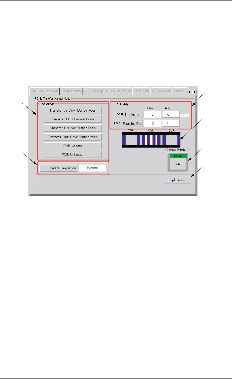
Fig. 2F107 "P.C.B. Transfer Manual Mode" Sheet
• Sheet Composition
*1 "Operation" Group Box
The following buttons are provided in this group box.
[Transfer In-Cnvr Buffer Posn] Button
When this button is pressed, the P.C.B. is transferred to the
input conveyor buffering position.
[Transfer PCB Locate Posn] Button
When this button is pressed, the P.C.B. is transferred to the
positioning location and positioned there.
[Transfer P-Cnvr Buffer Posn] Button
When this button is pressed, the P.C.B. is transferred to the
positioning conveyor buffering position.
0308-004 6-149
5.3 "P.E.C. Recog Camr & Beam Ofs" Tab
*1
*3
*5
*4
*6
*2

AHB01ESPP
[Transfer Out-Cnvr Buffer Posn] Button
When this button is pressed, the P.C.B. is transferred to the
output conveyor buffering position.
[PCB Locate] Button
When this button is pressed, the backup base is moved to the
P.C.B. locate position.
[PCB Unlocate] Button
When this button is pressed, the backup base is zeroed.
*2 [P.C.B. locate Sequence] Button
Select one of the following options as a P.C.B. positioning sequence.
Standard: Y Clamp deactivated, Z Clamp activated, and BPC Axis
activated
Z clamp & Y Pusher: Y Clamp activated once, Z Clamp activated,
and BPC Axis activated
*3 "B.P.C. Adj" Group Box
The following buttons are provided in this group box.
[PCB Thickness] Button
When this button is pressed, the "PCB Thickness" edit win-
dow opens, enabling the operator to enter a parameter as P.C.B.
thickness.
[B.P.C. Standby Pos] Button
When this button is pressed, the backup base standby posi-
tion is specified.
*4 Conveyor Status
The P.C.B. positions are expressed in white.
The blue areas represent sensors.
*5 "Control Switch" Group Box
Select the items (buttons) to be taught and press the [ON] button
entitled "MOVE". After that, press the [ENABLE] button on the op-
eration panel in 2 seconds. A teaching operation is performed on
the selected item.
*6 [Return] Button
When this button is pressed, the "P.C.B. Transfer Manual Mode"
sheet closes and the "P.E.C. Recog Camera & Beam Offset" tab
sheet resumes.
0308-004 6-150
5.3 "P.E.C. Recog Camr & Beam Ofs" Tab
AHB01ESPP
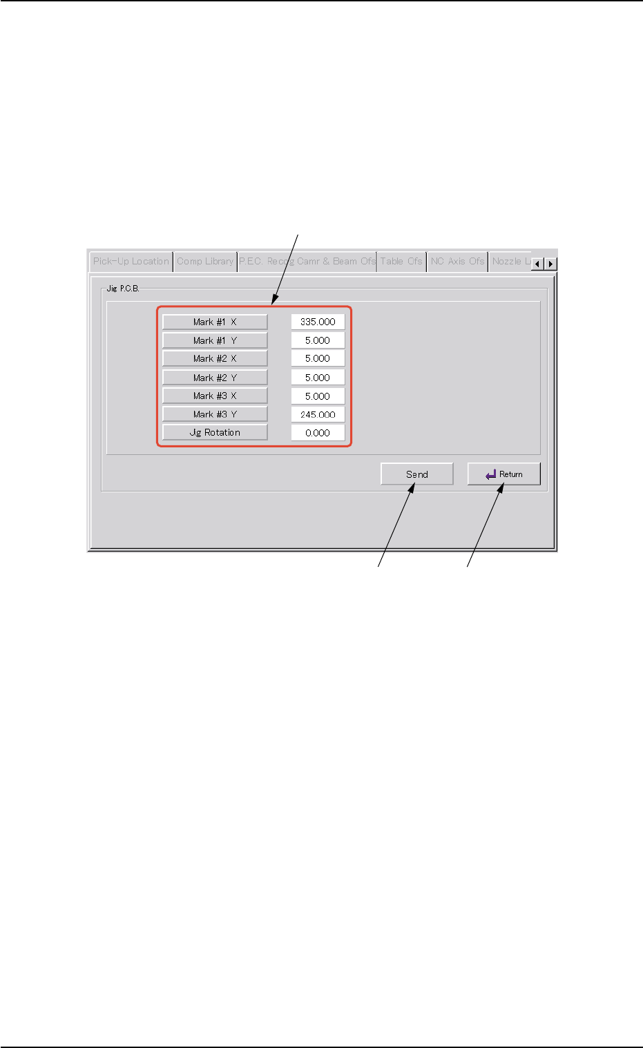
5.3.2 "Jig P.C.B." Sheet
This sheet enables the operator to set the jig P.C.B.
(In normal cases, it is not required any setting.)
• Sheet Layout
When the [Jig P.C.B.] button is pressed in the "P.E.C. Recog Camera &
Beam Offset" tab sheet, the following sheet appears.
Fig. 2F108 "Jig P.C.B." Sheet
• Sheet Composition
*1 "Jig P.C.B." Group Box
Select the jig P.C.B. data items to be set.
The following buttons are provided in this group box.
[Mark #1 X], [Mark #1 Y], [Mark #2 X], [Mark #2 Y], [Mark #3 X],
and [Mark #3 Y] Buttons : When each button is pressed, the cor-
responding edit window opens.
Enter a value that represents the X or
the Y coordinate of Mark #1, #2, or #3
in the range of "0 to 999.999 mm".
[Jig Rotation] Button : When this button is pressed, the "Jig
Rotation" edit window opens.
Enter the angle of the jig P.C.B. in the
range of "-9.999 to 9.999°".
0206-003 6-151
5.3 "P.E.C. Recog Camr & Beam Ofs" Tab
*1
*2
*3