2OM-1075-002.pdf - 第385页
AHB01ESPP 5.3.2 "Jig P .C.B." Sheet This sheet enables the operator to set the jig P .C.B. (In normal cases, it is not required any setting.) • Sheet Layout When the [Jig P .C.B.] button is pressed in the "…

AHB01ESPP
[Transfer Out-Cnvr Buffer Posn] Button
When this button is pressed, the P.C.B. is transferred to the
output conveyor buffering position.
[PCB Locate] Button
When this button is pressed, the backup base is moved to the
P.C.B. locate position.
[PCB Unlocate] Button
When this button is pressed, the backup base is zeroed.
*2 [P.C.B. locate Sequence] Button
Select one of the following options as a P.C.B. positioning sequence.
Standard: Y Clamp deactivated, Z Clamp activated, and BPC Axis
activated
Z clamp & Y Pusher: Y Clamp activated once, Z Clamp activated,
and BPC Axis activated
*3 "B.P.C. Adj" Group Box
The following buttons are provided in this group box.
[PCB Thickness] Button
When this button is pressed, the "PCB Thickness" edit win-
dow opens, enabling the operator to enter a parameter as P.C.B.
thickness.
[B.P.C. Standby Pos] Button
When this button is pressed, the backup base standby posi-
tion is specified.
*4 Conveyor Status
The P.C.B. positions are expressed in white.
The blue areas represent sensors.
*5 "Control Switch" Group Box
Select the items (buttons) to be taught and press the [ON] button
entitled "MOVE". After that, press the [ENABLE] button on the op-
eration panel in 2 seconds. A teaching operation is performed on
the selected item.
*6 [Return] Button
When this button is pressed, the "P.C.B. Transfer Manual Mode"
sheet closes and the "P.E.C. Recog Camera & Beam Offset" tab
sheet resumes.
0308-004 6-150
5.3 "P.E.C. Recog Camr & Beam Ofs" Tab
AHB01ESPP
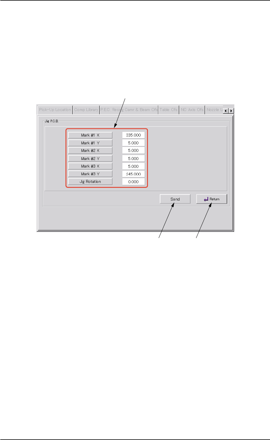
5.3.2 "Jig P.C.B." Sheet
This sheet enables the operator to set the jig P.C.B.
(In normal cases, it is not required any setting.)
• Sheet Layout
When the [Jig P.C.B.] button is pressed in the "P.E.C. Recog Camera &
Beam Offset" tab sheet, the following sheet appears.
Fig. 2F108 "Jig P.C.B." Sheet
• Sheet Composition
*1 "Jig P.C.B." Group Box
Select the jig P.C.B. data items to be set.
The following buttons are provided in this group box.
[Mark #1 X], [Mark #1 Y], [Mark #2 X], [Mark #2 Y], [Mark #3 X],
and [Mark #3 Y] Buttons : When each button is pressed, the cor-
responding edit window opens.
Enter a value that represents the X or
the Y coordinate of Mark #1, #2, or #3
in the range of "0 to 999.999 mm".
[Jig Rotation] Button : When this button is pressed, the "Jig
Rotation" edit window opens.
Enter the angle of the jig P.C.B. in the
range of "-9.999 to 9.999°".
0206-003 6-151
5.3 "P.E.C. Recog Camr & Beam Ofs" Tab
*1
*2
*3

AHB01ESPP
*2 [Send] Button
When this button is pressed after each parameter related to the jig
P.C.B. is specified, the parameter is sent to the machine side.
Whenever each parameter is changed, be sure to press
the [Send] button.
*3 [Return] Button
When this button is pressed, the "Jig P.C.B." sheet closes and the
"P.E.C. Recog Camera & Beam Offset" tab sheet resumes.
0206-003 6-152
Note
5.3 "P.E.C. Recog Camr & Beam Ofs" Tab