2OM-1075-002.pdf - 第394页
AHB01ESPP 5 . 7 "Cmpnt Fxd Camr Mag" T ab The corresponding tab sheet enables the operator to perform the teach- ing operation on the magnification offset of the component recognition camera (fixed camera). The…

AHB01ESPP
[Mvt to Noz Attachment Posn] Button:
When this button is pressed, the head moves to the speci-
fied feeder No. (Fdr. No.) position.
*4 Set Status
When "All Beam (Incl. NC Axis) Heads Zero" is completed, the back-
ground color of "All Beam Zero" turns green. (Otherwise, the back-
ground has no color.)
(a) When each device is not zeroed and the teaching op-
erations are performed, note that the offset values may
not be taught correctly.
(b) Before performing a teaching operation, be sure to zero
all beams.
*5 Fdr. No.
When this button is pressed, the "Fdr. No." edit window opens. En-
ter the feeder No. to which the head must be moved, using the ten-
key pad.
*6 Offset Values
Displayed are the current values and the adjusted ones after teach-
ing.
*7 [Mnl Noz Chng] Button
When this button is pressed, the "Mnl Noz Chng" sheet appears.
Refer to "4.3 "Nozzle Change" Tab" for details.
*8 [Clear Adj.] Button
When pressed, this button clears the results of the teaching opera-
tion.
*9 [Cancel] Button
When pressed, this button cancels the results of the teaching op-
eration without reflecting them on the offset data.
*10 [End] Button
When this button is pressed, a "Confirmation" dialog box opens.
When the [YES] button is pressed, the results of the teaching op-
eration are reflected on the offset data and the dialog box closes.
*11 "Control Switch" Group Box
Select one of the teaching item selection buttons and press the [ON]
button (entitled "MOVE"). After that, press the [ENABLE] button on
the operation panel in 2 seconds. A teaching operation is performed
on the selected item.
5.6 "Nozzle Level Ofs" Tab
Note
0308-004 6-159
AHB01ESPP
5.7 "Cmpnt Fxd Camr Mag" Tab
The corresponding tab sheet enables the operator to perform the teach-
ing operation on the magnification offset of the component recognition
camera (fixed camera).
The offset values are calculated by recognizing the printed pattern on
the special jig P.C.B. (option) picked up by the special jig nozzle (option)
with the component recognition camera (fixed).
This teaching operation must be performed only by our service
personnel.
• Sheet Layout
When the "Cmpnt Fxd Camr Mag" tab is pressed in the "TEACHING"
window (submenu), the following tab sheet appears inside the window.
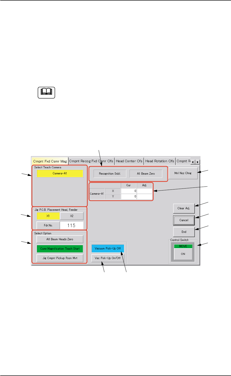
Fig. 2F112 "Cmpnt Fxd Camr Mag" Tab Sheet
• Sheet Composition
*1 "Select Teach Camera" Group Box
The fixed camera can be selected for teaching operations.
The following button is provided in this group box.
[Camera-A1] Button
Note
0206-003 6-160
5.7 "Cmpnt Fxd Camr Mag" Tab
*8
*9
*5
*10
*11
*12
*7
*1
*2
*3
*4
*6

AHB01ESPP
*2 "Jig P.C.B. Placement Head. Feeder" Group Box
[X1] and [X2] Buttons
Select the [X1] or the [X2] button to specify the head that will
pick up the special jig for teaching operations.
[Fdr. No.] Button
Specify the feeder No. (Fdr. No.) to which the head must be
shifted during the movement to the jig component pick-up po-
sition.
*3 "Select Option" Group Box
The following buttons are provided in this group box.
[All Beam Heads Zero] Button
When this button is pressed, all X/Y beam heads are zeroed.
[Camr. Magnification Teach Start] Button
When this button is pressed, the machine performs a teaching
operation on the magnification of the selected component rec-
ognition camera.
Before performing a teaching operation, pick up the special
jig and zero all beams.
[Jig Component Pickup Position Movement] Button
When this button is pressed, the head moves down to the pick-
up point over the designated feeder and stops.
*4 Set Status
When the "P.E.C. Dsbl." or the "Comp. Recognition Dsbl." check
box in the "Test Run" window is turned on (checked), the background
color of "Recognition Dsbl." turns light red. (No background color in
normal cases).
No recognition processing is made even if a teaching op-
eration is performed when each check box is turned on
(checked) in the "Test Run" window. Therefore, various
teaching operations will get incorrect results.
When "All Beam (Incl. NC Axis) Heads Zero" is completed, the back-
ground color of "All Beam Zero" turns green. (Otherwise, the back-
ground has no color.)
Note
Note
0308-004 6-161
5.7 "Cmpnt Fxd Camr Mag" Tab