2OM-1075-002.pdf - 第403页
AHB01ESPP • Preparation for T eaching Operations Nozzles Prepare either [EF01] or [EF02]. T eaching Plate (Component Recognition Offset Jig: JG-0085) (Standard Accessory Part) Handle this fragile jig very carefully . Fig…

AHB01ESPP
*5 Offset Values
Displayed are the current values and the adjusted ones after teach-
ing.
*6 [Manual Nozzle Change] Button
When this button is pressed, the "Nozzle Change" window appears.
Refer to "4.3 "Nozzle Change" Tab" for details.
*7 [Clear Adj.] Button
When pressed, this button clears the results of the teaching opera-
tion.
*8 [Cancel] Button
When pressed, this button ends the teaching operation without re-
flecting the teaching results on the offset data.
*9 [End] Button
When pressed, this button reflects the results of the teaching op-
eration on the offset data and exits from this session.
*10 "Control Switch" Group Box
Select the items (buttons) to be taught and press the [ON] button
entitled "MOVE". After that, press the [ENABLE] button on the op-
eration panel in 2 seconds. A teaching operation is performed on
the selected item.
0308-003 6-168
5.9 "Head Center Ofs" Tab
AHB01ESPP
• Preparation for Teaching Operations
Nozzles
Prepare either [EF01] or [EF02].
Teaching Plate
(Component Recognition Offset Jig: JG-0085)
(Standard Accessory Part)
Handle this fragile jig very carefully.
Fig. 2F115
2 types of patterns are printed through vapor deposition on the glass
for positional calculation.
• Teaching Procedure
(1) Attach the nozzle by hand.
(2) Attach the jig component (the teaching plate (component recogni-
tion offset jig)) to the position where the teaching plate is attached.
The printed side of the component recognition offset jig
should face downward.
(3) Confirm the following.
• The machine is powered.
• The safety doors are completely closed.
(3-1) Press the [Movement to Nozzle Placement Position] button
and bring the head over to the specified feeder No.
(3-2) Press the [Select Nozzle] button in the "Nozzle Change" sheet
to move Nozzle #1 to the "Noz #1" position.
Note
Note
0206-002 6-169
5.9 "Head Center Ofs" Tab
AHB01ESPP
(4) Open the safety door and manually attach the nozzle.
(5) Specify the head on which a teaching operation should be performed.
(6) Select the [All Beam Heads Zero] button and press the [ON] button
entitled "MOVE". After that, press the [ENABLE] button on the op-
eration panel in 2 seconds. All beams are zeroed.
(7) Select the [Teach Start] button and press the [ON] button entitled
"MOVE". After that, press the [ENABLE] button on the operation panel
in two seconds. The teaching operation starts.
The following series of teaching operations are performed automati-
cally.
The nozzle picks up the teaching plate from the place where the
teaching plate is attached.
The placement head moves to the component recognition cam-
era position.
The jig component is recognized with the component recogni-
tion camera.
(Posture in 4 Directions: 0°, 90°, 180° and 270°)
The teaching plate is returned to the original place (the place
where it was attached).
Fig. 2F116
0206-002 6-170
5.9 "Head Center Ofs" Tab
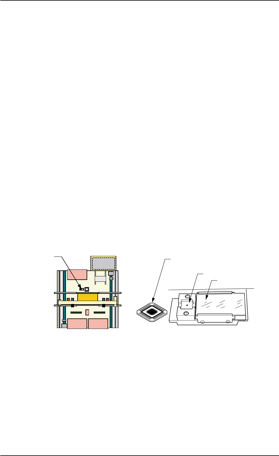
Teaching Plate
(Front Side of Machine)
Teaching Plate
(Component Recognition Offset Jig)
Position of Teaching Plate
Back Lighting Stage
Magnified View of Teaching Plate