2OM-1075-002.pdf - 第404页
AHB01ESPP (4) Open the safety door and manually attach the nozzle. (5 ) Specify the head on which a teaching operation should be performed. (6) Select the [All Beam Heads Zero] button and press the [ON] button entitled &…
AHB01ESPP
• Preparation for Teaching Operations
Nozzles
Prepare either [EF01] or [EF02].
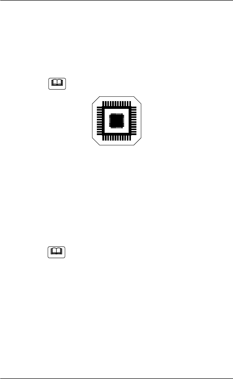
Teaching Plate
(Component Recognition Offset Jig: JG-0085)
(Standard Accessory Part)
Handle this fragile jig very carefully.
Fig. 2F115
2 types of patterns are printed through vapor deposition on the glass
for positional calculation.
• Teaching Procedure
(1) Attach the nozzle by hand.
(2) Attach the jig component (the teaching plate (component recogni-
tion offset jig)) to the position where the teaching plate is attached.
The printed side of the component recognition offset jig
should face downward.
(3) Confirm the following.
• The machine is powered.
• The safety doors are completely closed.
(3-1) Press the [Movement to Nozzle Placement Position] button
and bring the head over to the specified feeder No.
(3-2) Press the [Select Nozzle] button in the "Nozzle Change" sheet
to move Nozzle #1 to the "Noz #1" position.
Note
Note
0206-002 6-169
5.9 "Head Center Ofs" Tab
AHB01ESPP
(4) Open the safety door and manually attach the nozzle.
(5) Specify the head on which a teaching operation should be performed.
(6) Select the [All Beam Heads Zero] button and press the [ON] button
entitled "MOVE". After that, press the [ENABLE] button on the op-
eration panel in 2 seconds. All beams are zeroed.
(7) Select the [Teach Start] button and press the [ON] button entitled
"MOVE". After that, press the [ENABLE] button on the operation panel
in two seconds. The teaching operation starts.
The following series of teaching operations are performed automati-
cally.
The nozzle picks up the teaching plate from the place where the
teaching plate is attached.
The placement head moves to the component recognition cam-
era position.
The jig component is recognized with the component recogni-
tion camera.
(Posture in 4 Directions: 0°, 90°, 180° and 270°)
The teaching plate is returned to the original place (the place
where it was attached).
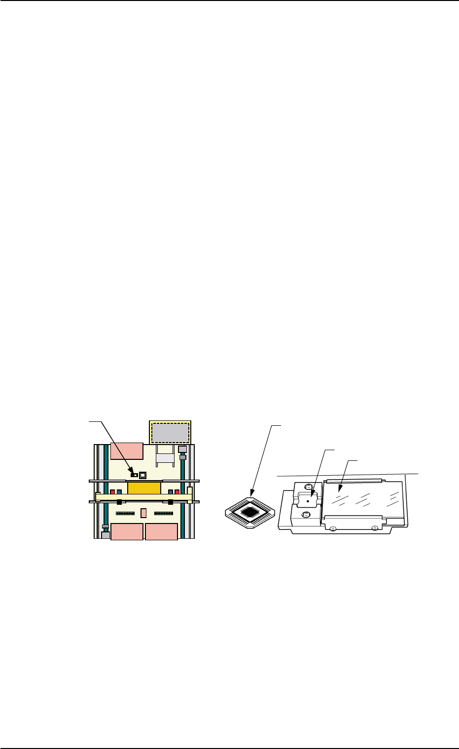
Fig. 2F116
0206-002 6-170
5.9 "Head Center Ofs" Tab
Teaching Plate
(Front Side of Machine)
Teaching Plate
(Component Recognition Offset Jig)
Position of Teaching Plate
Back Lighting Stage
Magnified View of Teaching Plate
AHB01ESPP
5.10 "Head Rotation Ofs" Tab
The corresponding tab enables the operator to perform the teaching
operation on the head rotation offset data.
This tab sheet allows the operator to perform a teaching operation on
the offset data that will be used to correct the angular deviation between
the nozzle clamp spring and the P.C.B. positioning reference with the
motor (for head rotational shaft) located at its origin.
Calculate the bending of the nozzle clamp spring with the component
recognition camera, regarding the special jig nozzle (option) as a com-
ponent.
The coarse step is taken to calculate an approximate angular deviation
and the accurate one to calculate an accurate angular deviation.
This teaching operation must be performed only by our service
personnel.
• Sheet Layout
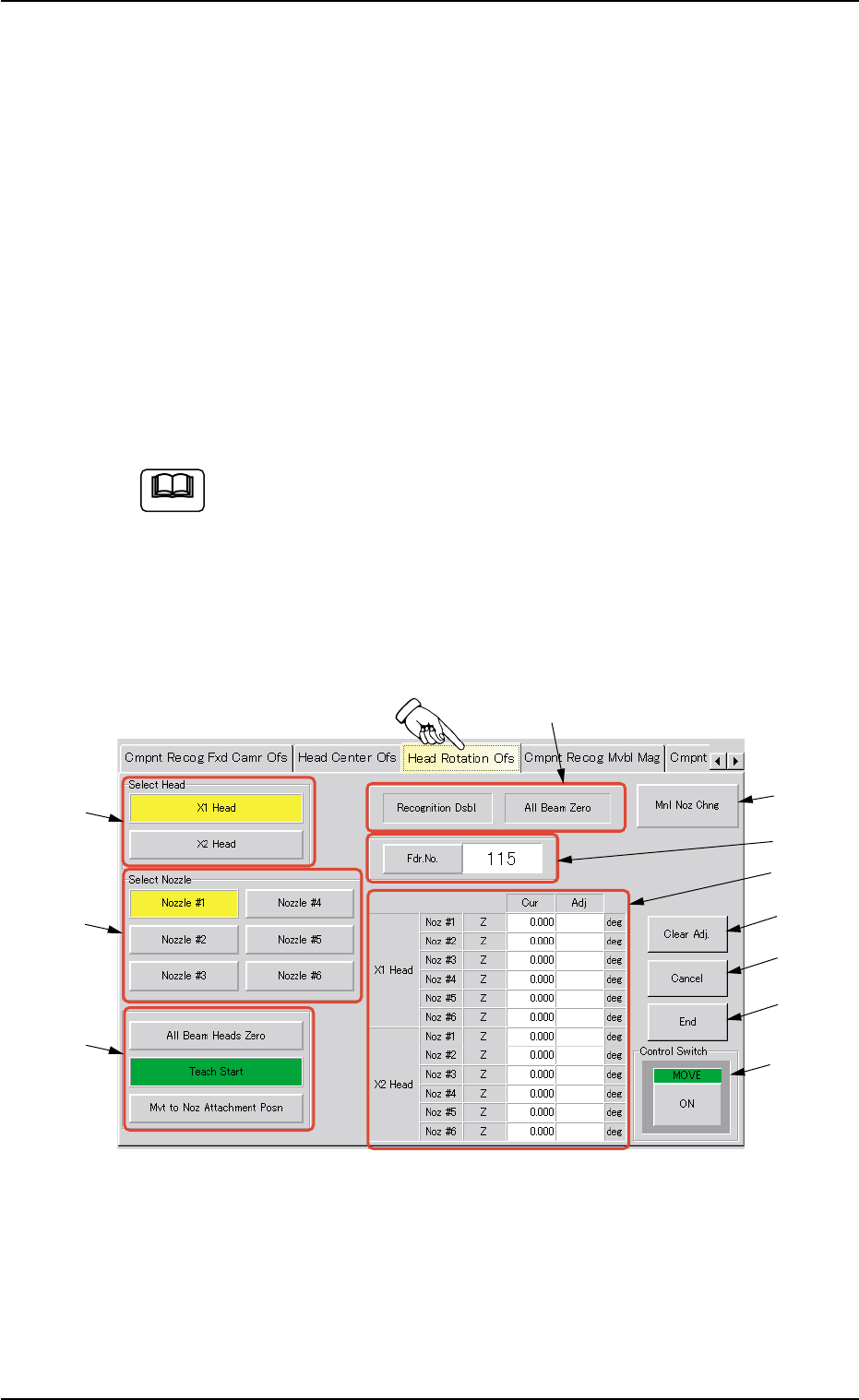
When the "Head Rotation Ofs" tab is pressed in the "TEACHING" win-
dow (submenu), the following tab sheet appears inside the window.
Fig. 2F117 "Head Rotation Ofs" Tab Sheet
Note
0206-002 6-171
5.10 "Head Rotation Ofs" Tab
*5
*11
*7
*8
*10
*9
*1
*2
*3
*4
*6