2OM-1075-002.pdf - 第408页
AHB01ESPP 5.1 1 "Cmpnt Recog Mvbl Mag" T ab The corresponding tab sheet enables the operator to perform the teach- ing operation on the magnification of the component recognition cam- era (movable). The offset …

AHB01ESPP
*5 [Fdr. No.] Button
When this button is pressed, the "Fdr. No." edit window opens. En-
ter the feeder No. to which the head must be moved, using the ten-
key pad.
*6 Offset Values
Displayed are the current values and the adjusted ones after teach-
ing.
*7 [Manual Nozzle Change] Button
When this button is pressed, the "Nozzle Change" window appears.
Refer to "4.3 "Nozzle Change" Tab" for details.
*8 [Clear Adj.] Button
When pressed, this button clears the results of the teaching opera-
tion.
*9 [Cancel] Button
When pressed, this button ends the teaching operation without re-
flecting the teaching results on the offset data.
*10 [End] Button
When pressed, this button reflects the results of the teaching op-
eration on the offset data and exits from this session.
*11 "Control Switch" Group Box
Select the items (buttons) to be taught and press the [ON] button
entitled "MOVE". After that, press the [ENABLE] button on the op-
eration panel in 2 seconds. A teaching operation is performed on
the selected item.
0308-003 6-173
5.10 "Head Rotation Ofs" Tab
AHB01ESPP
5.11 "Cmpnt Recog Mvbl Mag" Tab
The corresponding tab sheet enables the operator to perform the teach-
ing operation on the magnification of the component recognition cam-
era (movable).
The offset values are calculated by recognizing the printed pattern on
the special jig (option) picked up by the special jig nozzle (option) with
the component recognition camera (movable).
This teaching operation must be performed only by our service
personnel.
• Sheet Layout
When the "Cmpnt Recog Mvbl Mag" tab is pressed in the "TEACHING"
window (submenu), the following tab sheet appears inside the window.
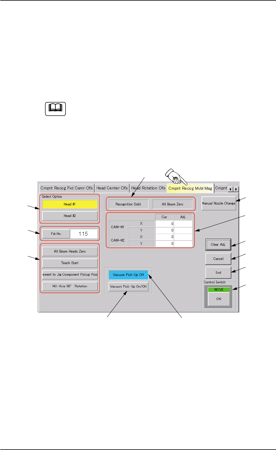
Fig. 2F118 "Cmpnt Recog Mvbl Mag" Tab Sheet
Note
0206-002 6-174
5.11 "Cmpnt Recog Mvbl Mag" Tab
*1
*2
*12
*9
*8
*10
*11
*3
*4
*5
*7
*6

AHB01ESPP
• Sheet Composition
*1 "Select Option" Group Box
The movable camera can be selected for teaching operations.
The following buttons are provided in this group box.
[Head #1] and [Head #2] Buttons
*2 [Fdr. No.] Button
When this button is pressed, the "Fdr. No." edit window opens. En-
ter the feeder No. to which the head must be moved, using the ten-
key pad.
*3 "Selection of Teaching Operation" Group Box
The following buttons are provided in this group box.
[All Beam Heads Zero] Button
When this button is pressed, all X/Y beams are zeroed.
[Teach Start] Button
When this button is pressed, a teaching operation is performed
on the selected movable camera.
[Movement to Jig Component Pickup Position] Button
When this button is pressed, the head moves down to the pick-
up point over the designated feeder and stops.
[NC-Axis 90° Rotation] Button
When this button is pressed, the jig component moves to the
front side of the movable camera after the NC axis is rotated by
90°. (It is not required to use this button in normal cases.)
*4 Set Status
When the "P.E.C. Dsbl." or the "Comp. Recognition Dsbl." check
box in the "Test Run" window is turned on (checked), the background
color of "Recognition Dsbl." turns light red. (No background color in
normal cases).
No recognition processing is made even if a teaching op-
eration is performed when the each check box is turned on
(checked) in the "Test Run" window. Therefore, various
teaching operations will get incorrect results.
When "All Beam (Incl. NC Axis) Heads Zero" is completed, the back-
ground color of "All Beam Zero" turns green. (Otherwise, the back-
ground has no color.)
Note
0308-003 6-175
5.11 "Cmpnt Recog Mvbl Mag" Tab