2OM-1075-002.pdf - 第433页
AHB01ESPP [T each Start] Button When this button is pressed, the machine performs a teaching op- eration on the selected item. [Movement to Nozzle Attachment Position] Button When this button is pressed, the head moves t…
AHB01ESPP
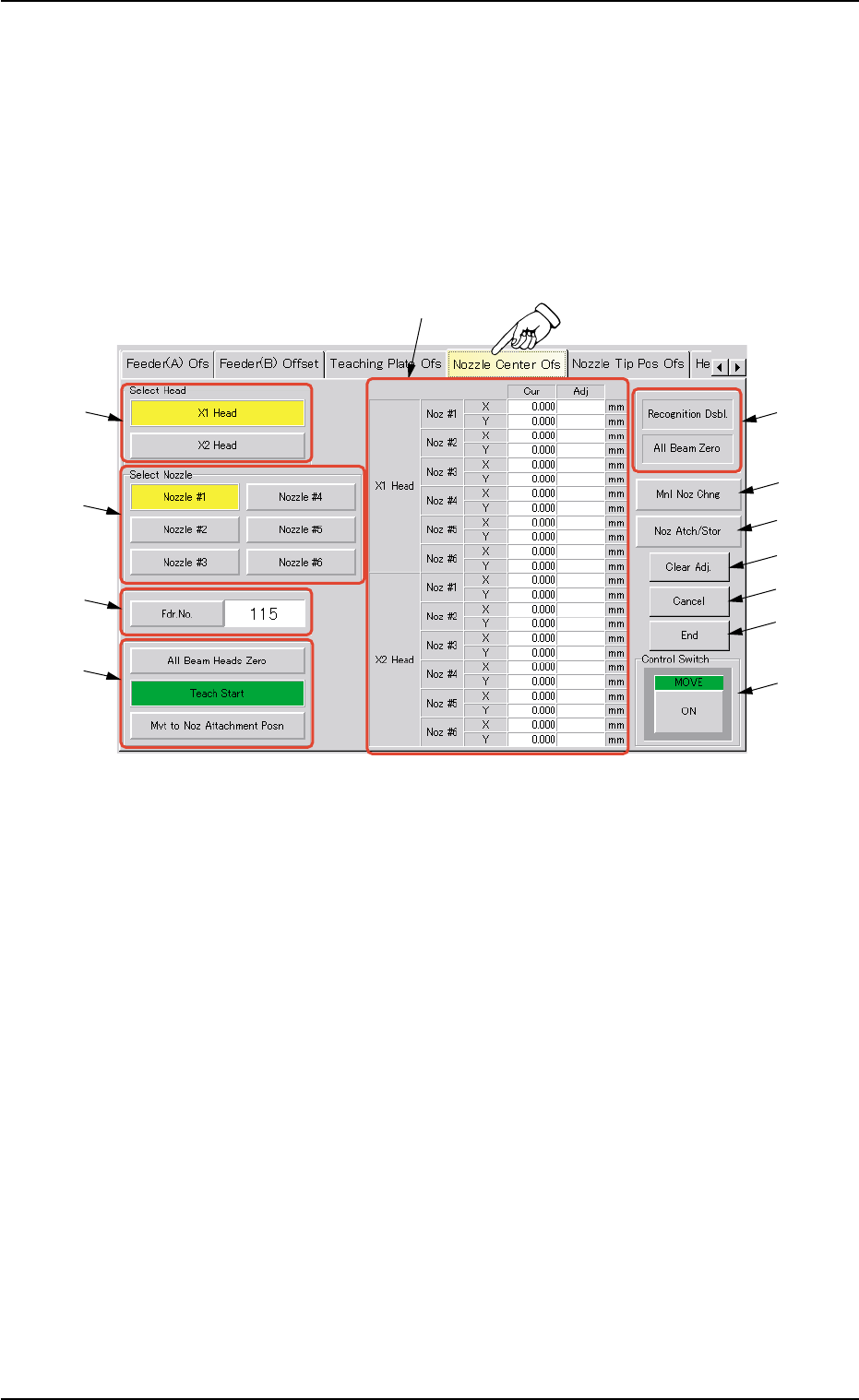
5.19 "Nozzle Center Ofs" Tab
The corresponding tab sheet enables the operator to perform the teach-
ing operation on the nozzle center offset.
••
••
• Sheet Layout
When the "Nozzle Center Ofs" tab is pressed in the "TEACHING" win-
dow (submenu), the following tab sheet appears inside the window.
Fig. 2F128 "Nozzle Center Ofs" Tab Sheet
••
••
• Sheet Composition
*1 "Select Head" Group Box
The following buttons are provided in this group box.
[X1 Head] and [X2 Head] Buttons
*2 "Select Nozzle" Group Box
Select the nozzle position to be taught.
*3 [Fdr. No.] Button and Text Box
When this button is pressed, the "Fdr. No." edit window opens. En-
ter the feeder No. to which the head must be moved, using the ten-
key pad.
*4 "Selection of Teaching Operation" Group Box
The following buttons are provided in this group box.
[All Beam Heads Zero] Button
When this button is pressed, all X/Y beams are zeroed.
0206-002 6-198
5.19 "Nozzle Center Ofs" Tab
*12
*11
*9
*5
*1
*2
*3
*4
*6
*7
*8
*10

AHB01ESPP
[Teach Start] Button
When this button is pressed, the machine performs a teaching op-
eration on the selected item.
[Movement to Nozzle Attachment Position] Button
When this button is pressed, the head moves to the specified feeder
No. (Fdr. No.) position.
*5 Offset Values
Displayed are the current values and the adjusted ones after teach-
ing.
*6 Set Status
When the "P.E.C. Dsbl." or the "Comp. Recognition Dsbl." check
box in the "Test Run" tab sheet is turned on (checked), the back-
ground color of "Recognition Dsbl." turns light red. (No background
color in normal cases).
No recognition processing is made even if a teaching op-
eration is performed when the each check box is turned on
(checked) in the "Test Run" window. Therefore, various
teaching operations will get incorrect results.
When "All Beam (Incl. NC Axis) Heads Zero" is completed, the back-
ground color of "All Beam Zero" turns green. (Otherwise, the back-
ground has no color.)
(a) When each device is not zeroed and the teaching op-
erations are performed, note that the offset values may
not be taught correctly.
(b) Before performing a teaching operation, be sure to zero
all beams.
*7 [Manual Nozzle Change] Button
When this button is pressed, the "Nozzle Change" sheet appears.
Refer to "4.3 "Nozzle Change" Tab" for details.
*8 [Nozzle Attachment/Storage] Button
When this button is pressed, the "Nozzle Attachment/Storage Test"
sheet appears.
Refer to "5.19.1 "Nozzle Attachment/Storage Test" Sheet" for de-
tails.
*9 [Clear Adj.] Button
When pressed, this button clears the results of the teaching opera-
tion.
*10 [Cancel] Button
When pressed, this button ends the teaching operation without re-
flecting the teaching results on the offset data.
5.19 "Nozzle Center Ofs" Tab
Note
Note
0308-003 6-199

AHB01ESPP
*11 [End] Button
When pressed, this button reflects the results of the teaching op-
eration on the offset data and exits from this session.
*12 "Control Switch" Group Box
Select the items (buttons) to be taught and press the [ON] button
entitled "MOVE". After that, press the [ENABLE] button on the op-
eration panel in two seconds. A teaching operation is performed on
the selected item.
••
••
• Preparation for Teaching Operations
Jig Nozzle (Option)
Fig. 2F129
••
••
• Teaching Procedure
(1) Press the [All Beam Heads Zero] button and the [ON] button (en-
titled "MOVE"). In 2 seconds, press the [ENABLE] button on the
operation panel to zero all beams.
(2) Select the head and nozzles to be taught.
(3) Select the position where the jig nozzle must be attached manually
by specifying the feeder No. in the "Fdr. No." text box.
(4) Press the [Mvt to Noz Attachment Posn] button to move the head to
the specified feeder No. position.
It is recommended that the nozzle to be taught should be selected
in the "Nozzle Change" sheet to make it easier to attach the jig nozzle
manually.
(5) Open the safety door and attach the jig nozzle manually.
(6) Close the safety door and zero all beams.
(7) Press the [Teach Start] button and the [ON] button (entitled "MOVE").
In 2 seconds, press the [ENABLE] button on the operation panel.
The automatic teaching operation starts.
(8) Follow the above procedure to perform teaching operations on
Nozzles #1 through #6 on 2 heads.
(9) Press the [End] button and save the data.
After these offset teaching operations, perform the nozzle stor-
age and attachment operations to confirm that the nozzles can
be stored or attached normally.
When the nozzles cannot be stored normally, the values speci-
fied as "Head Rotation Offsets", "Nozzle Stocker Position Off-
sets", and "Nozzle Stocker Offsets" may not be correct.
5.19 "Nozzle Center Ofs" Tab
0206-002 6-200
Note