2OM-1075-002.pdf - 第436页
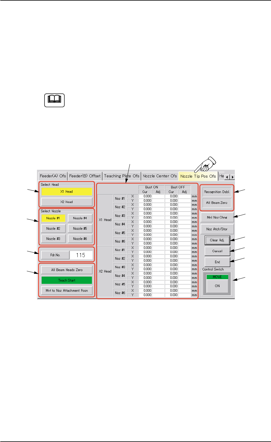
AHB01ESPP 5.20 "Nozzle Tip Pos Ofs" T ab The corresponding tab sheet enables the operator to perform a teach- ing operation on how far the nozzle tip position has deviated from the head rotational center positi…
AHB01ESPP
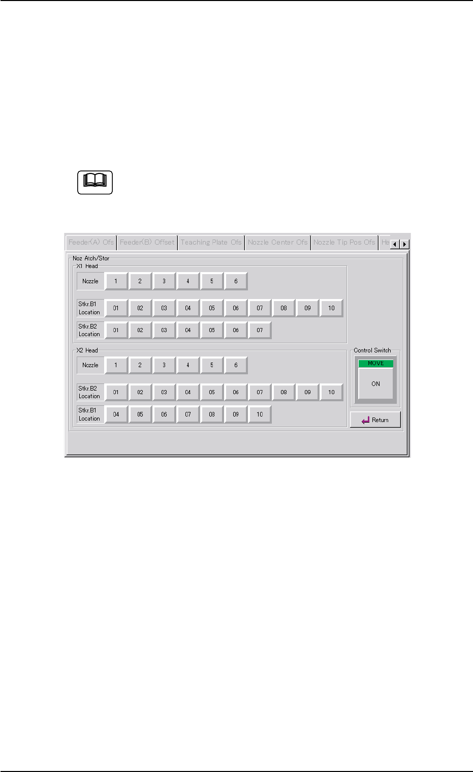
5.19.1 "Nozzle Attachment/Storage Test" Sheet
This sheet enables the operator to make a nozzle attachment/storage
test.
Select the nozzle to be tested and the stocker location and press the
[ON] button (entitled "MOVE"). In 2 seconds, press the [ENABLE] button
on the operation panel.
(It is not necessary to use this function in normal cases.)
If the teaching operation related to the nozzle stockers is not
completed normally, a collision will occur.
This function must be used only by our service personnel.
Fig. 2F130 "Nozzle Attachment/Storage Test" Sheet
5.19 "Nozzle Center Ofs" Tab
Note
0206-003 6-201
AHB01ESPP
5.20 "Nozzle Tip Pos Ofs" Tab
The corresponding tab sheet enables the operator to perform a teach-
ing operation on how far the nozzle tip position has deviated from the
head rotational center position.
The teaching operation is performed by automatically recognizing the
tip position of the nozzle on the head.
This teaching operation must be performed only by our service
personnel.
••
••
• Sheet Layout
When the "Nozzle Tip Pos Ofs" tab is pressed in the "TEACHING" win-
dow (submenu), the following tab sheet appears inside the window.
Fig. 2F131 "Nozzle Tip Pos Ofs" Tab Sheet
••
••
• Sheet Composition
*1 "Select Head" Group Box
The following buttons are provided in this group box.
[X1 Head] and [X2 Head] Buttons
*2 "Select Nozzle" Group Box
Select the nozzle position to be taught.
5.20 "Nozzle Tip Pos Ofs" Tab
Note
0206-003 6-202
*11
*10
*8
*6
*7
*9
*1
*2
*3
*4
*5

AHB01ESPP
*3 [Fdr. No.] Button and Text Box
When this button is pressed, the "Fdr. No." edit window opens. En-
ter the feeder No. to which the head must be moved, using the ten-
key pad.
*4 "Select Mode (Items to be taught)" Group Box
The following buttons are provided in this group box.
[All Beam Heads Zero] Button
When this button is pressed, all X/Y beams are zeroed.
[Teach Start] Button
When this button is pressed, the machine performs a teaching op-
eration on the selected item.
[Movement to Nozzle Attachment Position] Button
When this button is pressed, the head moves to the specified feeder
No. (Fdr. No.) position.
*5 Offset Values
Displayed are the current values and the adjusted ones after teach-
ing.
*6 Set Status
When the "P.E.C. Dsbl." or the "Comp. Recognition Dsbl." check
box in the "Test Run" tab sheet is turned on (checked), the back-
ground color of "Recognition Dsbl." turns light red. (No background
color in normal cases)
No recognition processing is made even if a teaching op-
eration is performed when the each check box is turned on
(checked) in the "Test Run" tab sheet. Therefore, various
teaching operations will get incorrect results.
When "All Beam (Incl. NC Axis) Heads Zero" is completed, the back-
ground color of "All Beam Zero" turns green. (Otherwise, the back-
ground has no color.)
(a) When each device is not zeroed and the teaching op-
erations are performed, note that the offset values may
not be taught correctly.
(b) Before performing a teaching operation, be sure to zero
all beams.
*7 [Manual Nozzle Change] Button
When this button is pressed, the "Nozzle Change" sheet appears.
Refer to "4.3 "Nozzle Change" Tab" for details.
5.20 "Nozzle Tip Pos Ofs" Tab
Note
Note
0308-004 6-203