2OM-1075-002.pdf - 第44页
5. Adjoining Pitch for T ape Feeder Installation 5 . 1 Minimum Adjoining Pitch Based on Guide Feeder T able 2A15 Left Side Minimum Adjoining Pitch Right Side Minimum Adjoining Pitch 1 Pitch = 22 mm Fig. 2A1 Shown in Fig.…
Nozzle
Nozzle Type
Note (a)
Note (b) Remarks
ID
Component
Applicable Components Part No.
Size
(For Reference) Part Name
(Referential
Values) (mm)
EF01 11 × 11 to Coils (11 or more)
20 × 20 QFP (14 to 20)
PLCC (14 to 20)
Other similar-shaped components
630 111 3869
NOZZLE (EF01)
Notes: (a) As for "Component Size (mm)" in the table, a han-
dling test may be required depending on the shape,
etc., of a component.
(b) As for "Applicable Components for Reference", the
dimensions of the components differ depending on
the component makers. The dimensions are shown
only for your reference.
(c) Consult our marketing department for details of
nozzles other than those listed in the table.
(d) There is a possibility that the component and the
structure interfere with each other when the
vacuum nozzle not suitable for the component
shape is used.
Be sure to use the vacuum nozzle suitable for the
component shape.
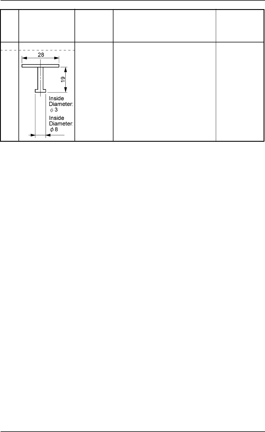
The following shows the details of the applicable
nozzles.
Length : Max. 19 × 0.05 mm
Outside Diameter: Max. φ18 mm
4. Vacuum Nozzle Types
0206-001 1-26 AHB01ESPP
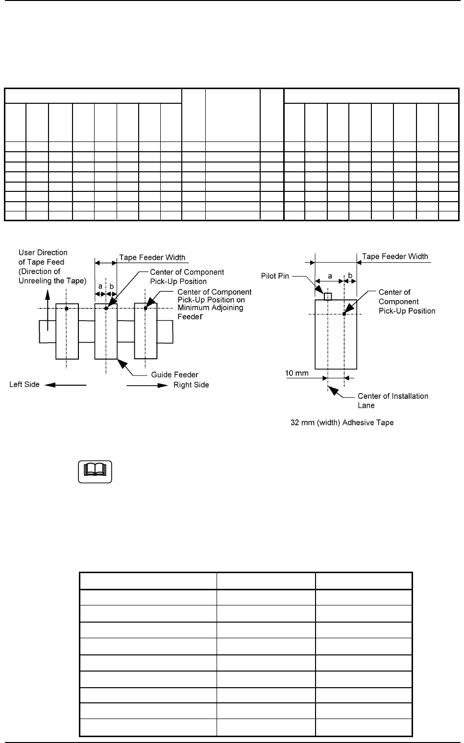
5. Adjoining Pitch for Tape Feeder Installation
5.1 Minimum Adjoining Pitch Based on Guide Feeder
Table 2A15
Left Side Minimum Adjoining Pitch Right Side Minimum Adjoining Pitch
1 Pitch = 22 mm
Fig. 2A1
Shown in Fig. 2A1 is a view based on the direction in which the
feeder is installed.
5.2 Installable Feeder Slot Nos. at Both Feeder Base
Ends
Feeder-Installed Lanes Table 2A16
Types of Feeders Left End Right End
8 mm (width) No Regulation No Regulation
12 mm (width) No Regulation No Regulation
16 mm (width) No Regulation No Regulation
24 mm (width) No Regulation No Regulation
32 mm (width) Embossed 1 Lane Impossible No Regulation
32 mm (width) Adhesive 1 Lane Impossible 1 Lane Impossible
44 mm (width) 1 Lane Impossible 1 Lane Impossible
56 mm (width) 2 Lane Impossible 1 Lane Impossible
72 mm (width) 1 Lane Impossible 2 Lane Impossible
5. Adjoining Pitch for Tape Feeder Installation
Note
72
mm
(width)
3
3
3
4
3
4
4
4
56
mm
(width)
3
3
3
4
3
4
4
4
32
mm
(width)
Em-
bossed
2
2
2
3
2
3
4
4
72
mm
(width)
3
4
4
4
4
4
4
5
56
mm
(width)
3
3
3
4
4
4
4
4
0308-002 1-27 AHB01ESPP
32
mm
(width)
Adhe-
sive
3
3
3
4
3
4
4
4
32
mm
(width)
Adhe-
sive
2
2
2
2
3
3
3
3
44
mm
(width)
2
2
3
3
3
4
4
4
24
mm
(width)
2
2
2
3
2
3
3
4
16
mm
(width)
2
2
2
3
2
3
3
4
8,12
mm
(width)
1
2
2
2
2
3
3
3
a
mm
13.8
15
19
33.8
32
39.8
45.8
53.8
b
mm
8
12
15
20.6
23
27.1
33.1
41.1
Guide Feeder
8, 12 mm (width)
16 mm (width)
24 mm (width)
32 mm (width) Embossed
32 mm (width) Adhesive
44 mm (width)
56 mm (width)
72 mm (width)
44
mm
(width)
3
3
3
3
4
4
4
4
32
mm
(width)
Em-
bossed
2
3
3
3
4
3
4
4
24
mm
(width)
2
2
2
2
3
3
3
3
16
mm
(width)
2
2
2
2
3
2
3
3
8,12
mm
(width)
1
2
2
2
3
2
3
3
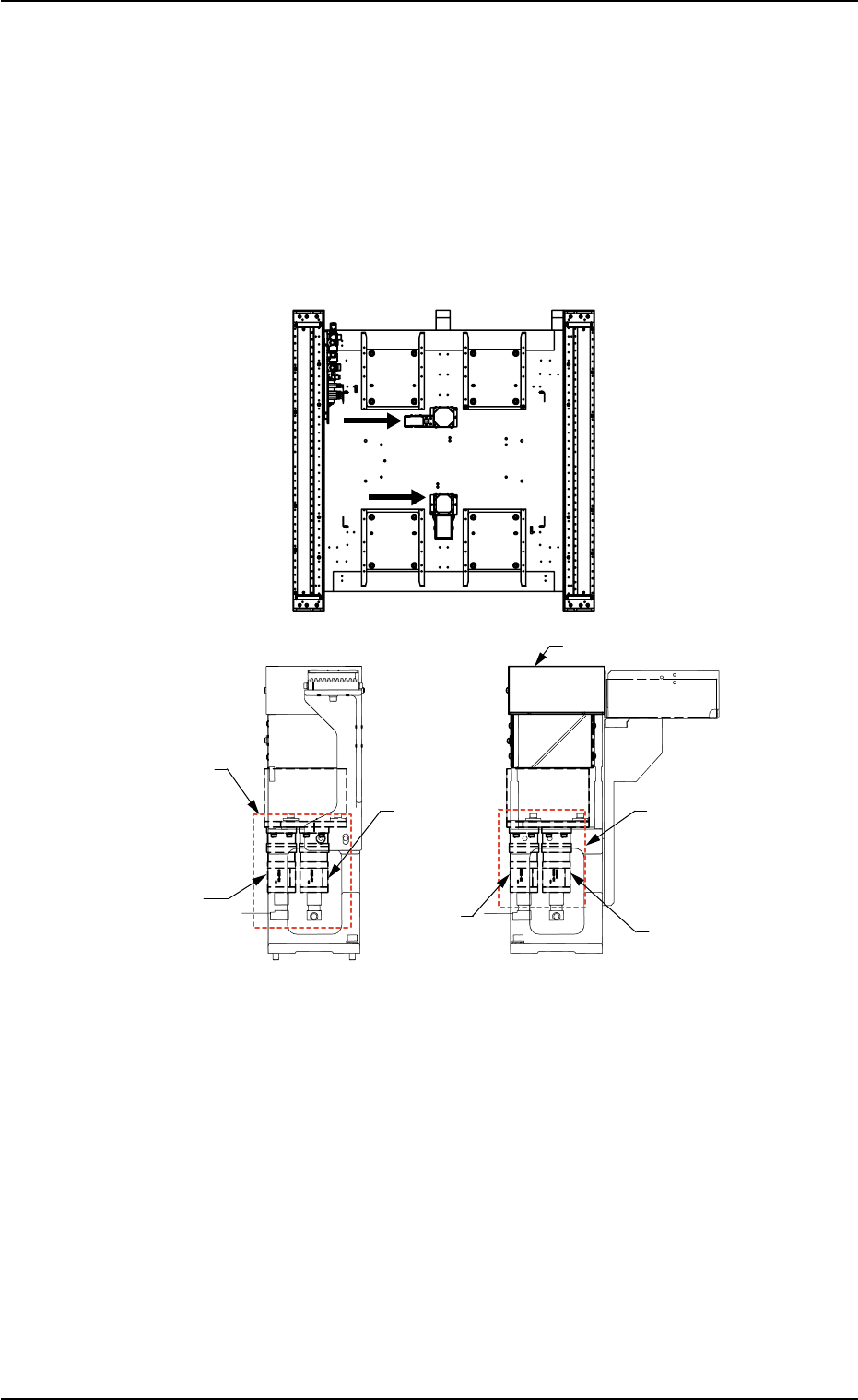
6. Fixed Recognition Cameras
6.1 Types of Fixed Recognition Cameras
There are following types for fixed recognition cameras.
View B View C
Fig. 2A2 Compound View Units (Option) on Front and Rear Sides of Machine
6. Fixed Recognition Cameras
0206-001 1-28 AHB01ESPP
C
B
(Rear Side of Machine)
(Front Side of Machine)
Lighting Unit (LG-5010)
Compound View Unit
(Option)
CAM-A1
(Large View)
CAM-A2
(Minimum
View)
CAM-B1
(Large View)
Compound View Unit
(Option)
CAM-B2
(Minimum
View)