2OM-1075-002.pdf - 第45页
6. Fixed Recognition Cameras 6 . 1 T ypes of Fixed Recognition Cameras There are following types for fixed recognition cameras. View B View C Fig. 2A2 Compound View Units (Option) on Front and Rear Sides of Machine 6. Fi…
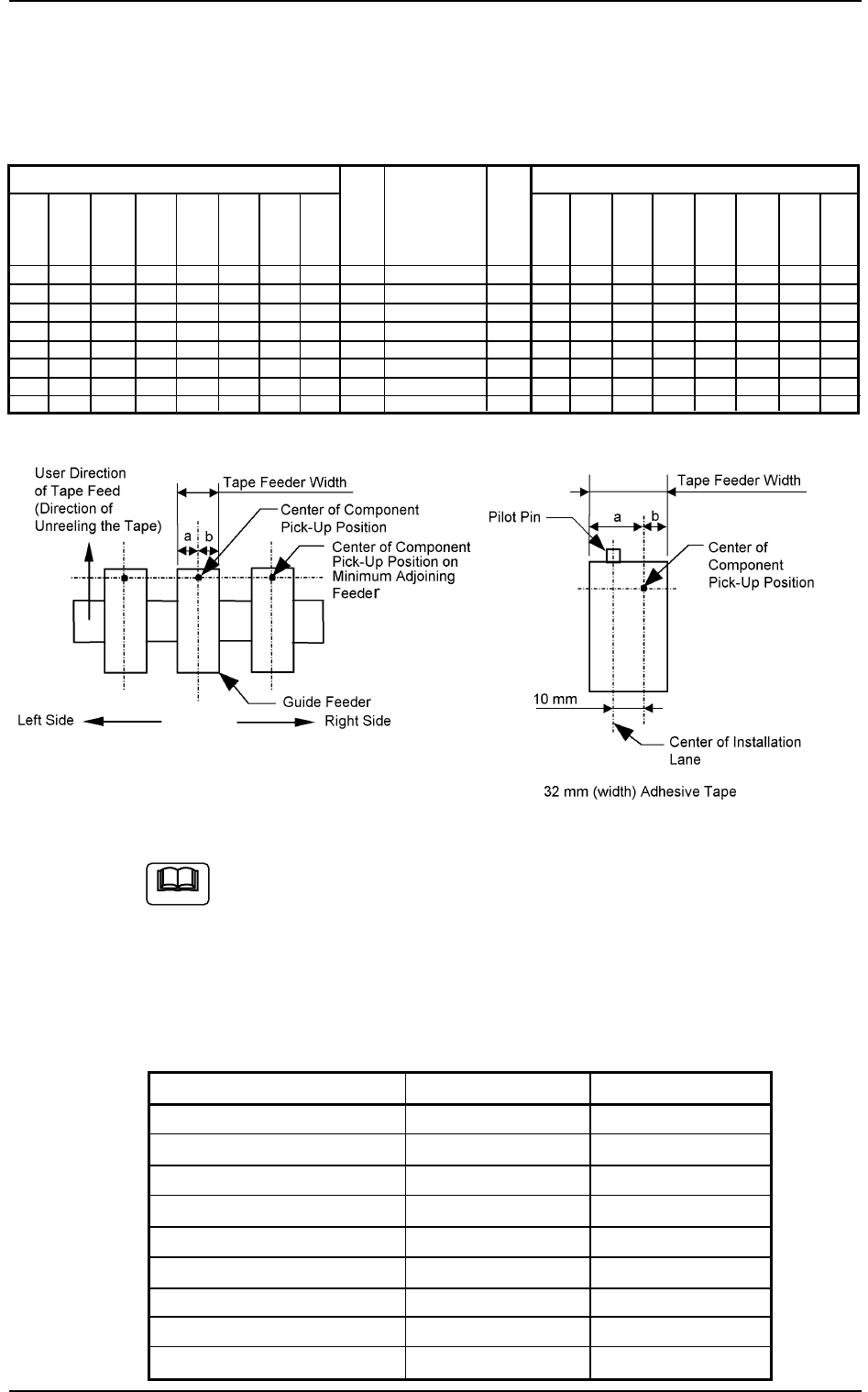
5. Adjoining Pitch for Tape Feeder Installation
5.1 Minimum Adjoining Pitch Based on Guide Feeder
Table 2A15
Left Side Minimum Adjoining Pitch Right Side Minimum Adjoining Pitch
1 Pitch = 22 mm
Fig. 2A1
Shown in Fig. 2A1 is a view based on the direction in which the
feeder is installed.
5.2 Installable Feeder Slot Nos. at Both Feeder Base
Ends
Feeder-Installed Lanes Table 2A16
Types of Feeders Left End Right End
8 mm (width) No Regulation No Regulation
12 mm (width) No Regulation No Regulation
16 mm (width) No Regulation No Regulation
24 mm (width) No Regulation No Regulation
32 mm (width) Embossed 1 Lane Impossible No Regulation
32 mm (width) Adhesive 1 Lane Impossible 1 Lane Impossible
44 mm (width) 1 Lane Impossible 1 Lane Impossible
56 mm (width) 2 Lane Impossible 1 Lane Impossible
72 mm (width) 1 Lane Impossible 2 Lane Impossible
5. Adjoining Pitch for Tape Feeder Installation
Note
72
mm
(width)
3
3
3
4
3
4
4
4
56
mm
(width)
3
3
3
4
3
4
4
4
32
mm
(width)
Em-
bossed
2
2
2
3
2
3
4
4
72
mm
(width)
3
4
4
4
4
4
4
5
56
mm
(width)
3
3
3
4
4
4
4
4
0308-002 1-27 AHB01ESPP
32
mm
(width)
Adhe-
sive
3
3
3
4
3
4
4
4
32
mm
(width)
Adhe-
sive
2
2
2
2
3
3
3
3
44
mm
(width)
2
2
3
3
3
4
4
4
24
mm
(width)
2
2
2
3
2
3
3
4
16
mm
(width)
2
2
2
3
2
3
3
4
8,12
mm
(width)
1
2
2
2
2
3
3
3
a
mm
13.8
15
19
33.8
32
39.8
45.8
53.8
b
mm
8
12
15
20.6
23
27.1
33.1
41.1
Guide Feeder
8, 12 mm (width)
16 mm (width)
24 mm (width)
32 mm (width) Embossed
32 mm (width) Adhesive
44 mm (width)
56 mm (width)
72 mm (width)
44
mm
(width)
3
3
3
3
4
4
4
4
32
mm
(width)
Em-
bossed
2
3
3
3
4
3
4
4
24
mm
(width)
2
2
2
2
3
3
3
3
16
mm
(width)
2
2
2
2
3
2
3
3
8,12
mm
(width)
1
2
2
2
3
2
3
3
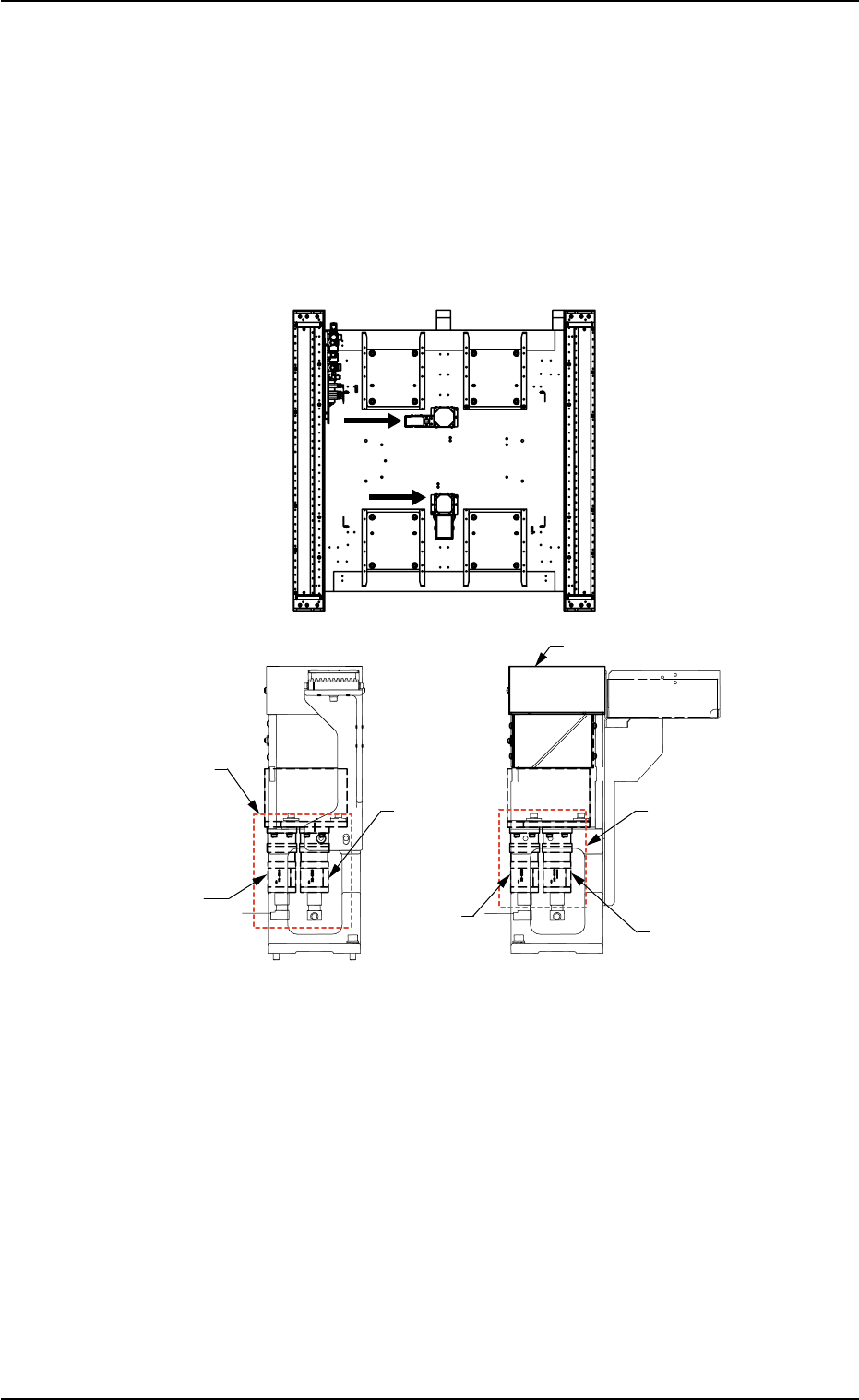
6. Fixed Recognition Cameras
6.1 Types of Fixed Recognition Cameras
There are following types for fixed recognition cameras.
View B View C
Fig. 2A2 Compound View Units (Option) on Front and Rear Sides of Machine
6. Fixed Recognition Cameras
0206-001 1-28 AHB01ESPP
C
B
(Rear Side of Machine)
(Front Side of Machine)
Lighting Unit (LG-5010)
Compound View Unit
(Option)
CAM-A1
(Large View)
CAM-A2
(Minimum
View)
CAM-B1
(Large View)
Compound View Unit
(Option)
CAM-B2
(Minimum
View)

Table 2A17
Name Model Description Installation Remarks
Fixed Recognition Camera A1 CM-5010 Large View Normal
(CAM-A1)
Fixed Recognition Cameras CM-5011 Minimum/Large Option
A2/A1 (CAM-A2/A1) (Compound View)
Fixed Recognition Camera B1 CM-5010 Large View Option
(CAM-B1)
Fixed Recognition Cameras CM-5011 Minimum/Large Option
B2/B1 (CAM-B2/B1) (Compound View)
Consult our marketing department or sales agency about the
installation of the fixed recognition cameras (option), the com-
bination, etc.
6.1 Types of Fixed Recognition Cameras
0206-001 1-29 AHB01ESPP
Installation on
Rear Side of
Machine
Installation on
Rear Side of
Machine
Installation on
Front Side of
Machine
The lighting unit
(LG-5010) must
be added.
Installation on
Front Side of
Machine
The lighting unit
(LG-5010) must
be added.
Note