2OM-1075-002.pdf - 第451页
AHB01ESPP 7.1.4 "Motor Cont (MCB)" T ab The corresponding tab sheet enables the operator to view the input/ output statuses of the motor control (MCB). • Sheet Layout When the "Motor Cont (MCB)" tab i…
AHB01ESPP
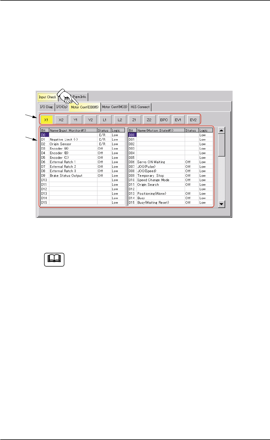
7.1.3 "Motor Cont (EB005)" Tab
The corresponding tab sheet enables the operator to view the input/
output statuses of the motor control (EB005).
• Sheet Layout
When the "Motor Cont (EB005)" tab is pressed in the "Input Check" tab
sheet, the following tab sheet appears.
Fig. 2F136 "Motor Cont (EB005)" Tab Sheet
(Provided with Multi-Layer Tray Feeder 2)
The tab sheet may look different, depending on which options
are selected.
• Sheet Composition
*1 Motor Axis Buttons
Press one of the following buttons to change the contents (status
indication) to be displayed in "*2".
[X1] Button, [X2] Button, [Y1] Button, [Y2] Button
[L1] Button, [L2] Button, [Z1] Button, [Z2] Button
[BPC] Button, [EV1] Button (Option), [EV2] Button (Op-
tion)
*2 Status Indication
The following information will be displayed for "Input Monitor #1",
"Operating Status", "Error Status 1", "Error Status 2", and "Error
Status 3".
Bit : Displayed are the bit Nos.
Status : Displayed are the bit statuses.
Logic : Displayed are the logical values of the bits.
0206-003 6-212
7.1 "Input Check" Tab
*1
*2
Note
AHB01ESPP
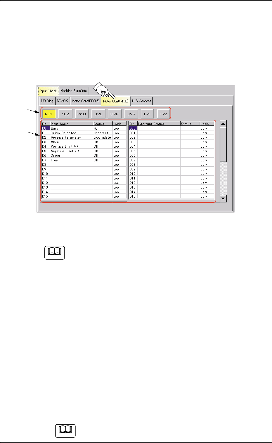
7.1.4 "Motor Cont (MCB)" Tab
The corresponding tab sheet enables the operator to view the input/
output statuses of the motor control (MCB).
• Sheet Layout
When the "Motor Cont (MCB)" tab is pressed in the "Input Check" tab
sheet, the following tab sheet appears.
Fig. 2F137 "Motor Cont (MCB)" Tab Sheet
(Provided with Multi-Layer Tray Feeder 2)
The tab sheet may look different, depending on which options
are selected.
• Sheet Composition
*1 Motor Axis Buttons
Press one of the following buttons to change the contents (status
indication) to be displayed in "*2".
[NC1] Button, [NC2] Button, [PWC] Button, [CVL] Button
[CVP] Button, [CVR] Button, [TV1] Button (Option), [TV2]
Button (Option)
*2 Status Indication
The following information will be displayed for each input, interrupt
factor, and factor to stop the machine.
Bit : Displayed are the bit Nos.
Status : Displayed are the bit statuses.
Logic : Displayed are the logical values of the bits.
If you move down the scroll box within the scroll bar, the
"HLS Status" group box becomes visible.
Note
0206-003 6-213
7.1 "Input Check" Tab
Note
*1
*2
AHB01ESPP
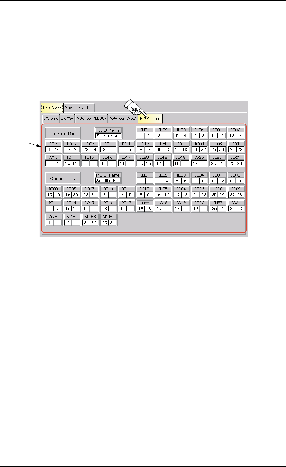
7.1.5 "HLS Connect" Tab
The corresponding tab sheet enables the operator to view how the HLS
boards are connected.
• Sheet Layout
When the "HLS Connect" tab is pressed in the "Input Check" tab sheet,
the following tab sheet appears.
Fig. 2F138 "HLS Connect" Tab Sheet
• Sheet Composition
*1 Status of HLS Connection
Displayed are how the HLS boards are connected.
0206-003 6-214
7.1 "Input Check" Tab
*1