2OM-1075-002.pdf - 第54页
1.2.2 Component Supply and Pick-Up Each Feeder: Component Supply • Each feeder (the tape, the vibratory stick, or the multi-layer tray feeder) specified in the pattern program sends out the components to the supply posit…
1.2.1 Preparation for Component Picks
P.C.B. Positioning Section:
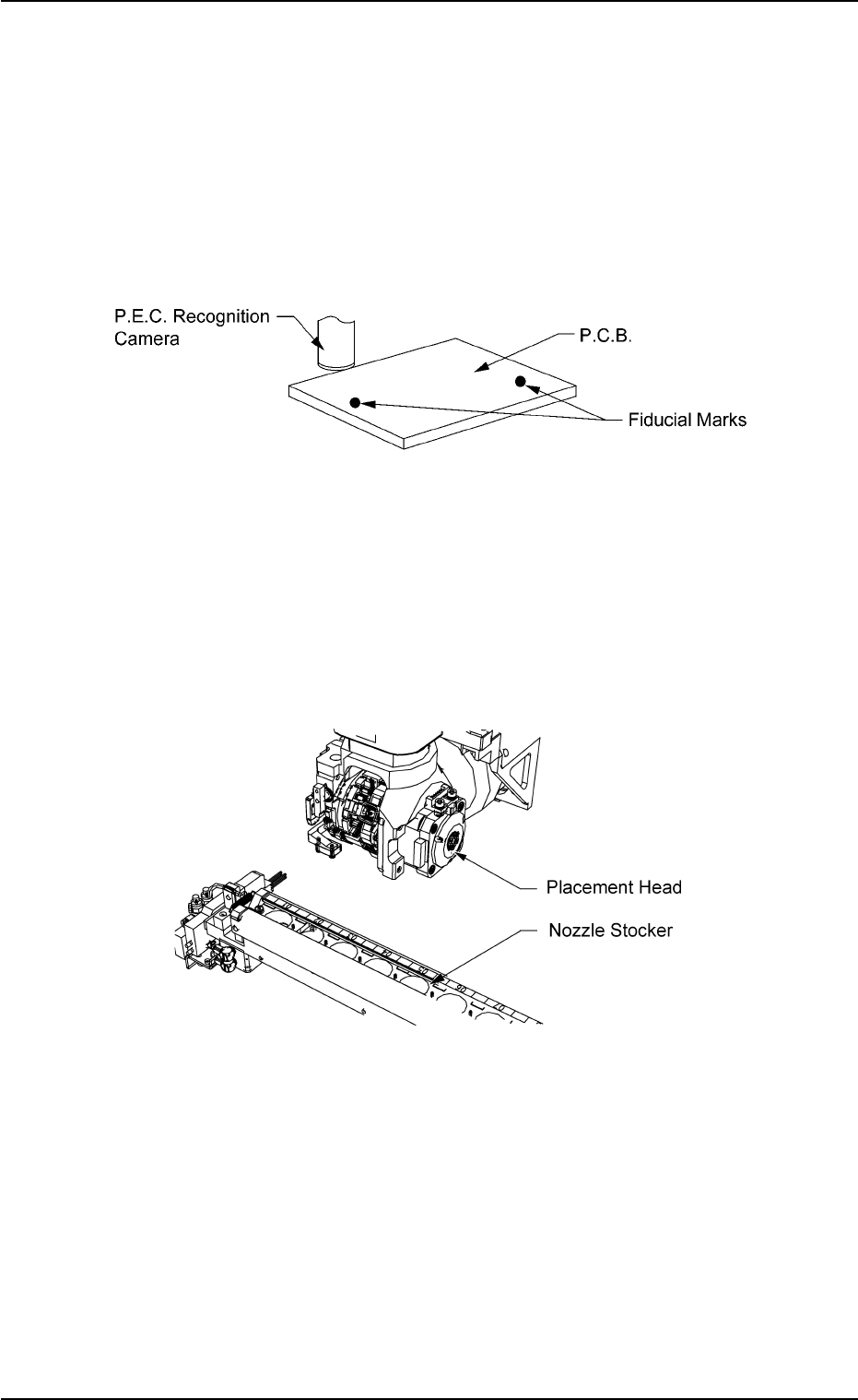
P.E.C. Recognition (Recognition of Placement Position)
• The P.E.C. camera is used to detect through P.E.C. recognition if
the placed components are shifted from the correct position or not.
Note: This will be performed only when specified in the pattern
program.
Fig. 2B5 P.E.C. Recognition
Nozzle Stocker: Nozzle Change
• A vacuum nozzle is selected for components and the attached
nozzle is replaced with the proper one.
The vacuum nozzle on the placement head is stored in the nozzle
stocker and the required one is taken out of the stocker.
Fig. 2B6 Nozzle Change
0206-002 2 -4 AHB01ESPP
1.2 Component Placement (starting with preparation for component picks)
1.2.2 Component Supply and Pick-Up
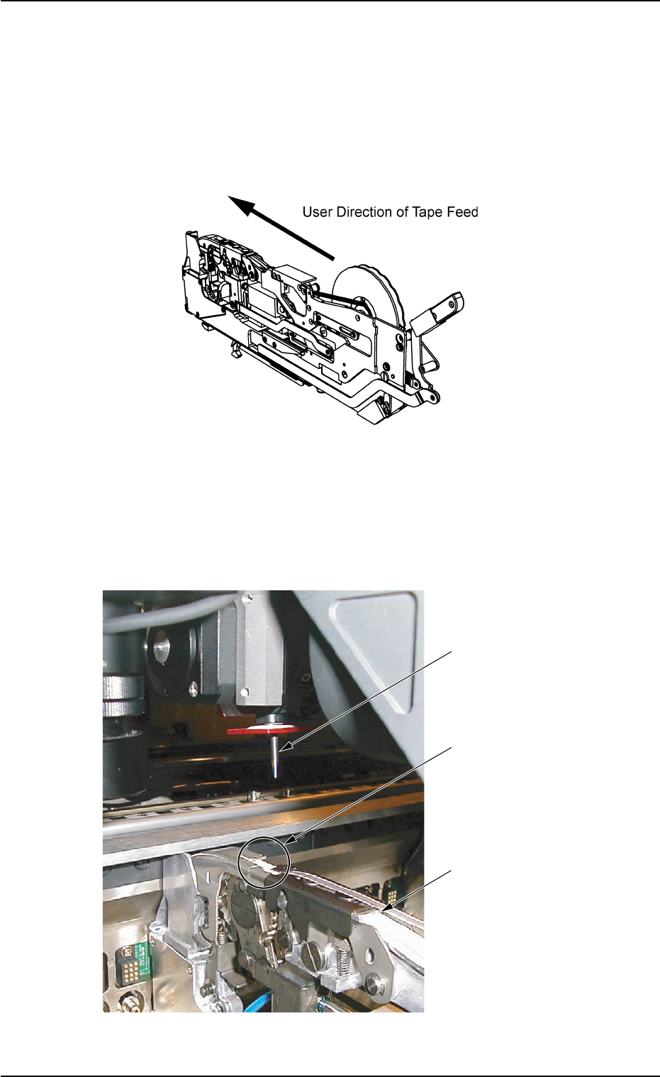
Each Feeder: Component Supply
• Each feeder (the tape, the vibratory stick, or the multi-layer tray
feeder) specified in the pattern program sends out the components
to the supply position, using the tape feed mechanism.
Fig. 2B7 Component Supply
Feeder Base: Component Pick-Up
• The heads move to the supply position of each feeder and the
vacuum nozzles pick up the components.
Fig. 2B8 Component Pick-Up
0206-002 2 -5
AHB01ESPP
1.2 Component Placement (starting with preparation for component picks)
Supply Position
Vacuum Nozzle
Tape Feeder
1.2.3 Preparation for Component Placement
Movable and Fixed Cameras:
Image Capture for Component Recognition and Component
Recognition
• The movable or the fixed camera captures an image of the compo-
nent for recognition.
The component recognition camera is automatically selected ac-
cording to the component library data.
• The machine is provided with two component recognition systems
- "Back Lighting Recognition System" and "Front Lighting Recogni-
tion System". The lighting method specified in the component li-
brary is automatically selected.
The following component recognition takes place.
(1) Component Detection
All components can be detected.
(2) Component Inspection
Each inspection is made according to the component library.
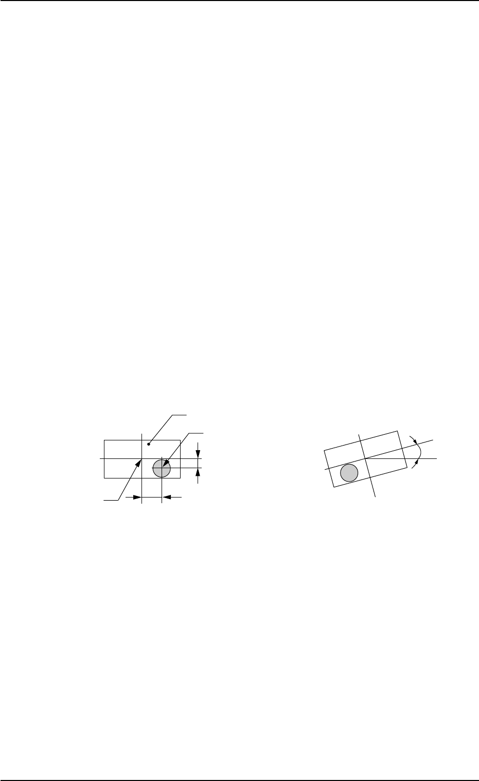
(3) Measurement of Positional Deviation (X, Y) and Angular
Deviation (θ) between Component Recognition Camera
Center and Component Center
Fig. 2B9 State of Component Picked Up by Vacuum Nozzle
0206-003 2 -6
AHB01ESPP
1.2 Component Placement (starting with preparation for component picks)
Component
Vacuum Nozzle
Component Center
Y
X
θ
Positional Deviation X and Y
Angular Deviation θ
(deviation from correct direction)