2OM-1075-002.pdf - 第59页
Component Storage Box: Component Discharge • When a recognition error occurs during the component recogni- tion, the head moves to the component storage box and discharges the error-caused component. Fig. 2B15 Component …
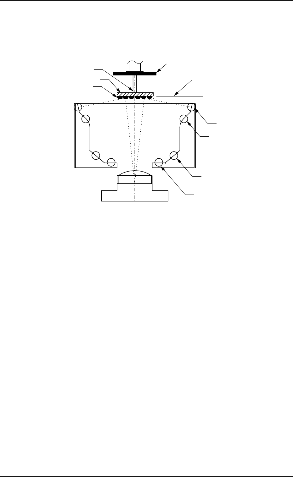
(3) Front Lighting Recognition System (For BGA Components)
The figure shows the sectional view of the recognition unit and
the flow of recognition light in the front lighting recognition
system (for BGA components).
Fig. 2B14
The light emitted from the front lighting (upper) reflects to the balls lo-
cated on the bottom of the BGA component.
The reflected light enters into the CCD camera through the monocular.
The captured images look like doughnuts.
That is, the CCD camera is used to detect where the BGA balls are or
whether or not the balls exist.
• Correction of Recognition
Theta (Angle) Correction
The picked component is adjusted to the angle (placement direction) of
placement specified in the pattern program by rotating the head.
At this time, the angular deviation (θ) detected through component rec-
ognition is also corrected.
0206-003 2 -9
AHB01ESPP
1.2 Component Placement (starting with preparation for component picks)
Ball
Front Lighting (Lower)
Front Lighting (Center)
Fixed Back Lighting
Component Recognition Camera
BGA Component
Nozzle
Diffusion Plate
Focused Plane
Front Lighting (Upper)
(CCD Camera)
Monocular
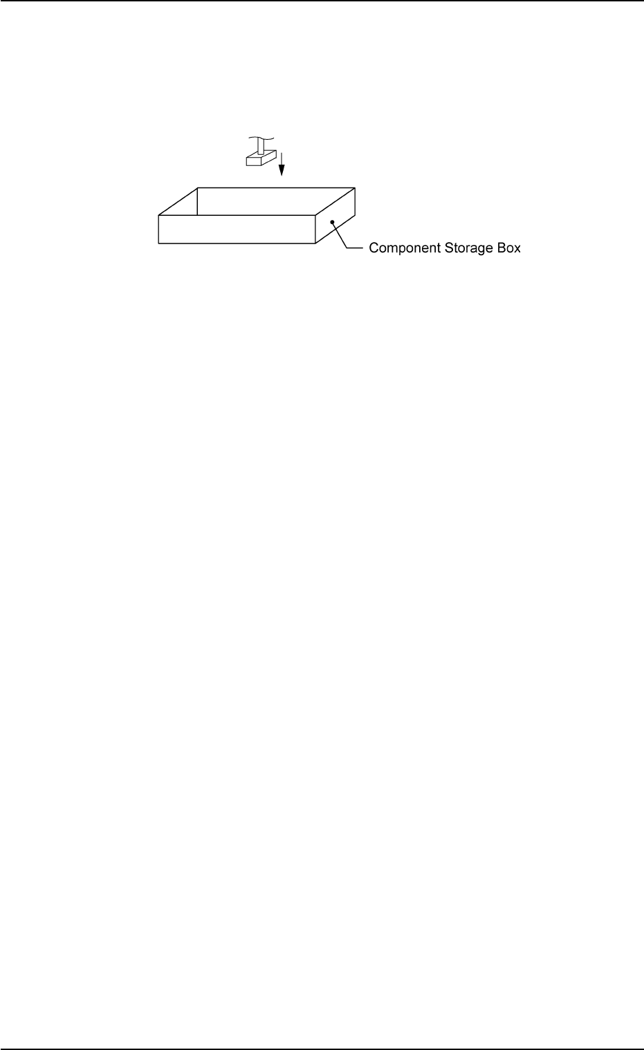
Component Storage Box: Component Discharge
• When a recognition error occurs during the component recogni-
tion, the head moves to the component storage box and discharges
the error-caused component.
Fig. 2B15 Component Discharge
0206-003 2-10 AHB01ESPP
1.2 Component Placement (starting with preparation for component picks)
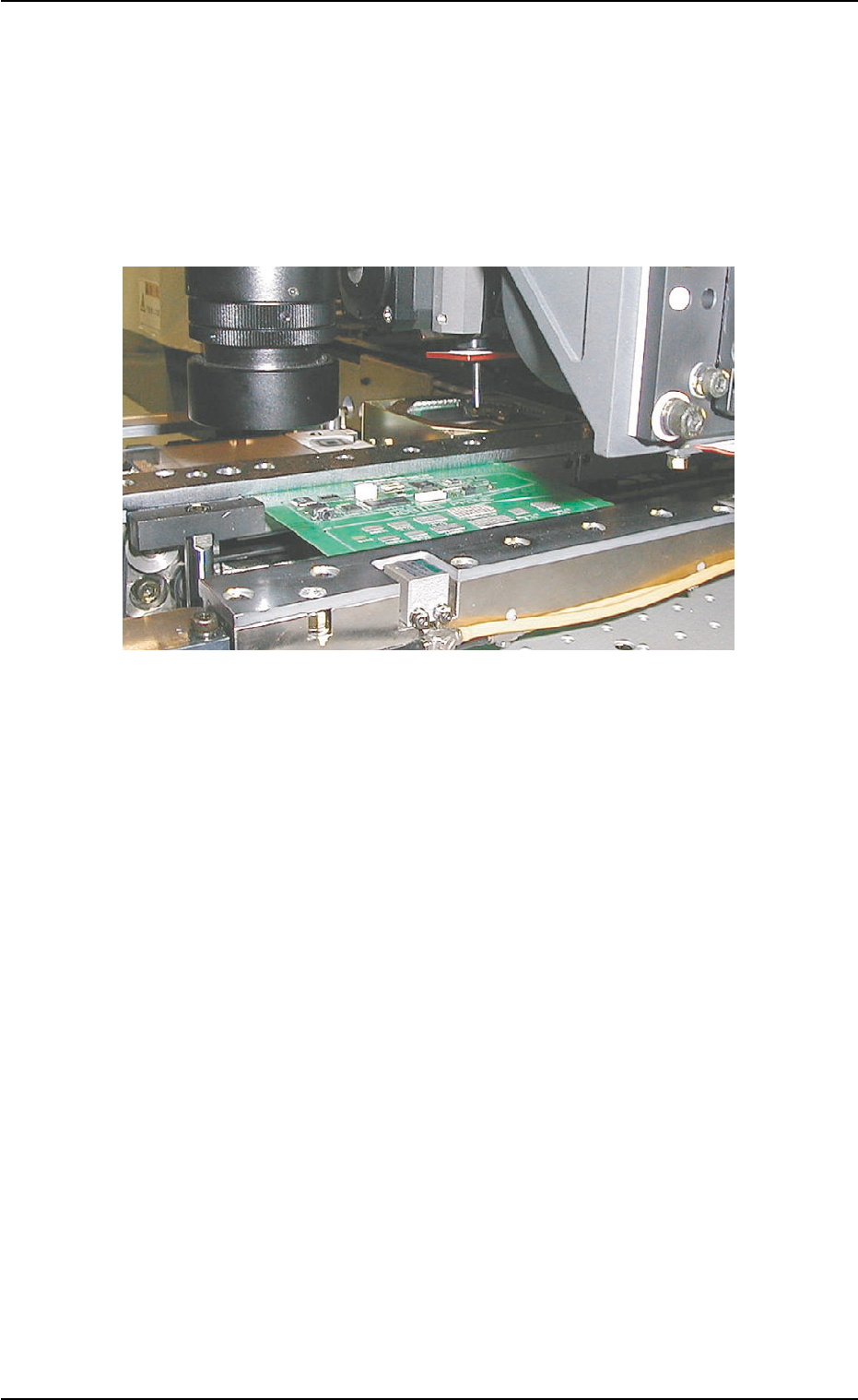
1.2.4 Component Placement
P.C.B. Positioning Section: Component Placement
• The heads move to the area over the placement coordinates on the
P.C.B. specified in the pattern program.
The deviation (X, Y) of the pick-up position (measured through the
component recognition) is also corrected at this time.
Fig. 2B16 Movement to Area over Placement Coordinates
• When a component is placed, the lowest limit of the required nozzle
is controlled according to the component library data.
• The vacuum valve closes, air blows out from the nozzle, and the
component is placed on the P.C.B.
0206-002 2-11
AHB01ESPP
1.2 Component Placement (starting with preparation for component picks)