2OM-1075-002.pdf - 第66页
• How to use the P .E.C. recognition function T able 2B4 Step Reference 1. Confirmation of Specifications "2. Specifications" in "Section 1" 2. Creating a Pattern Program (1) "2.1 T ypes of P .C.…
2.4 P.E.C. Recognition Function
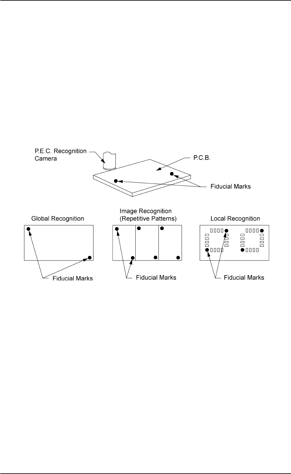
In normal cases, two fiducial marks are put on a P.C.B. and the coordi-
nate data and positional deviation are detected by the P.E.C. recognition
camera. This function automatically corrects placement positions of
components according to the recognized positional deviation.
• There are three kinds of P.E.C. recognition functions - "Global", "Im-
age", and "Local". The global recognition function covers all positional
deviation over one P.C.B. and is used to correct it. The image recog-
nition function is used to correct positional deviation for each indi-
vidual patterns. The local recognition function is used to correct posi-
tional deviation for each component placement point.
Fig. 2B22
0206-002 2-16 AHB01ESPP
2.4 P.E.C. Recognition Function

• How to use the P.E.C. recognition function
Table 2B4
Step Reference
1. Confirmation of Specifications "2. Specifications" in "Section 1"
2. Creating a Pattern Program
(1) "2.1 Types of P.C.B.’s and Required Data" in "Section
2" of "Vol. 3: Programming and Machine Data"
(2) "2.3 Operation Data" in "Section 2" of "Vol. 3: Program-
ming and Machine Data"
• A02 P.C.B. Recognition Data
• A03 P.C.B. Recognition Mark Data
(3) "2.5 Placement Data" in "Section 2" of "Vol. 3: Program-
ming and Machine Data"
• C02_02 Unit P.C.B. B.B.R. Recognition
(4) "3. Example of Pattern Program Creation" in "Section
2" of "Vol. 3: Programming and Machine Data"
• "3.2 Single Pattern (P.E.C. Recognition Function
Enabled)"
• "3.4 Repetitive Patterns (Unit P.C.B. B.B.R. Enabled)"
(a) When P.C.B.’s are positioned on the P.C.B. positioning sec-
tion and mechanical accuracy in P.C.B. positioning varies
due to variation in outer dimensions of P.C.B.’s, the P.E.C.
recognition function can work effectively to reduce such
inaccuracy.
(b) Fiducial marks are put to detect the position of placement
patterns. Therefore, the positional relation between fidu-
cial marks and placement patterns must be constant. Oth-
erwise, the placement accuracy cannot be improved.
0107-001 2-17 AHB01ESPP
2.4 P.E.C. Recognition Function
Note
2.5 Automatic Feeder Axis Adjustment Function
When a component is picked up by the nozzle and shifted from the
correct pick-up position, this function uses the recognition system to
correct the deviation for accurate component placement.
By feeding the recognized amount of correction back to the pick-up po-
sition, the pick-up position can also be brought close to the specified
one.
Table 2B5
Step Reference
1. Setting of Operation Mode "3.3 "Opn. Mode" Tab" in "Section 5"
2.6 Conveyor Width Automatic Adjustment Function
When the current program is changed, the conveyor width is automati-
cally adjusted.
Table 2B6
Step Reference
1. Program Change Operation "Section 3 Program Change Operation"
2.7 File Operation
The placement data can be saved on a 3.5-inch floppy disk in the FD
(floppy disk drive) of the front service panel or can be loaded from the
floppy disk.
• The data stored on the hard disk (HD) of the main machine can be
saved on a floppy disk (FD).
A created file can be loaded, using the network terminal (option).
• The data stored on a floppy disk (FD) can be loaded to the main
machine side.
A file of the pattern program data created on the network terminal
(option) can be loaded to the machine side. (Excl. the component
library data)
• The pattern program data on a floppy disk (FD) can be deleted.
Table 2B7
Step Reference
1. File Operation
"8. "FILE OPERATION" Window (Submenu)" in "Section
6"
0206-002 2-18 AHB01ESPP
2.5 Automatic Feeder Axis Adjustment Function