2OM-1075-002.pdf - 第73页
(3) Set "Enable" or "Disable" as the alternate feeder mode for each individual feeders. In the "Altn Fdr Mode (Enable)" tab sheet, it is possible to check how the alternate feeder mode is wo…
2.13 Feeder Alternate Function
0308-002 2-23 AHB01ESPP
(2) Make the "Altn Fdr Mode" tab sheet appear in the "OPN. MODE"
window (submenu) that opens after the [OPN. MODE] button on the
submenu bar of the "AUTO RUN" window is pressed.
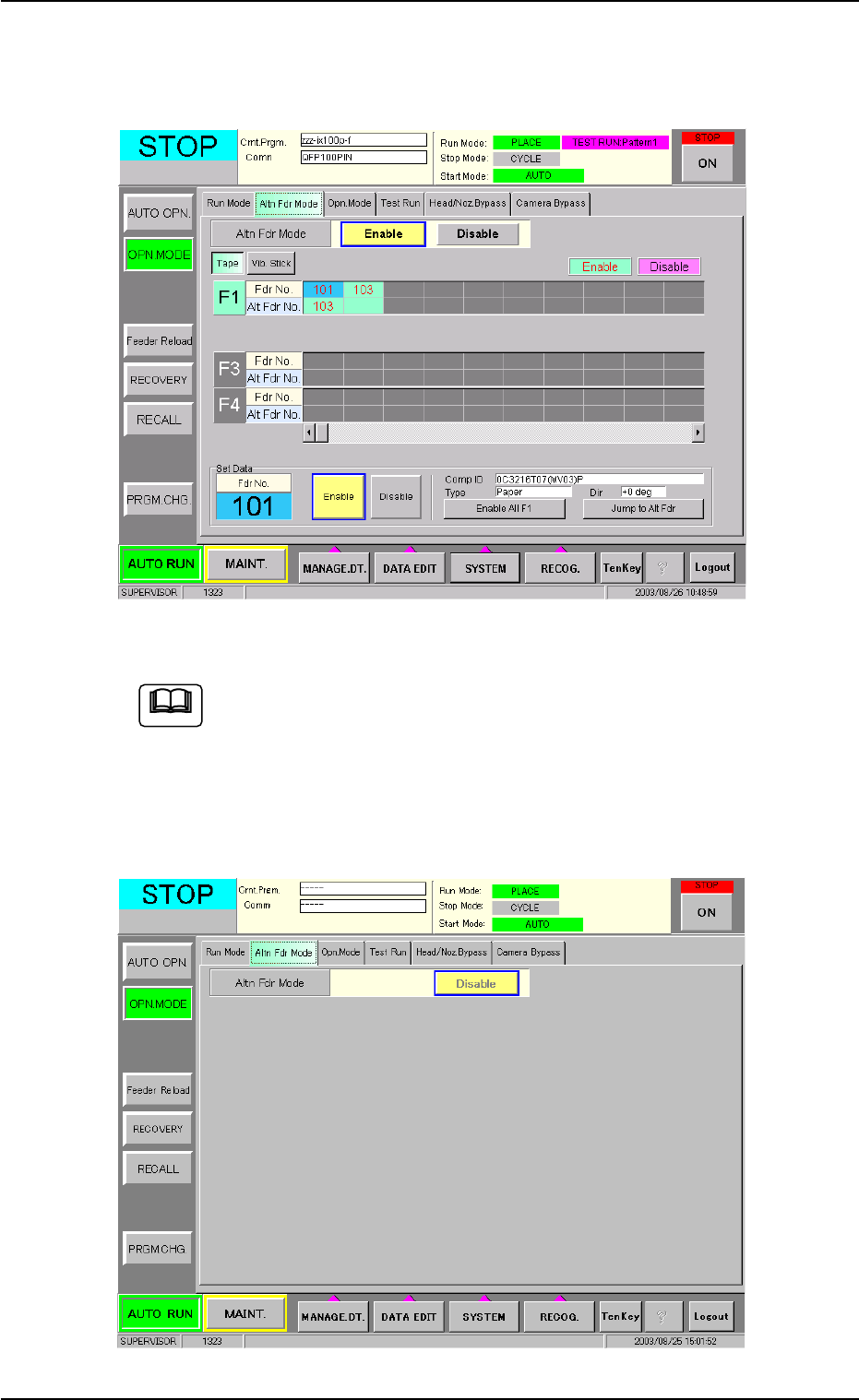
Fig. 2B25 "Altn Fdr Mode (Enable)" Tab Sheet
Fig. 2B25 shows the contents of the "Altn Fdr Mode" tab sheet
that appear when "Enable" is set in the "Feeder Alternate" text
box of the "Placement Feeder Location" tab sheet in the "Pat-
tern Program" edit window.
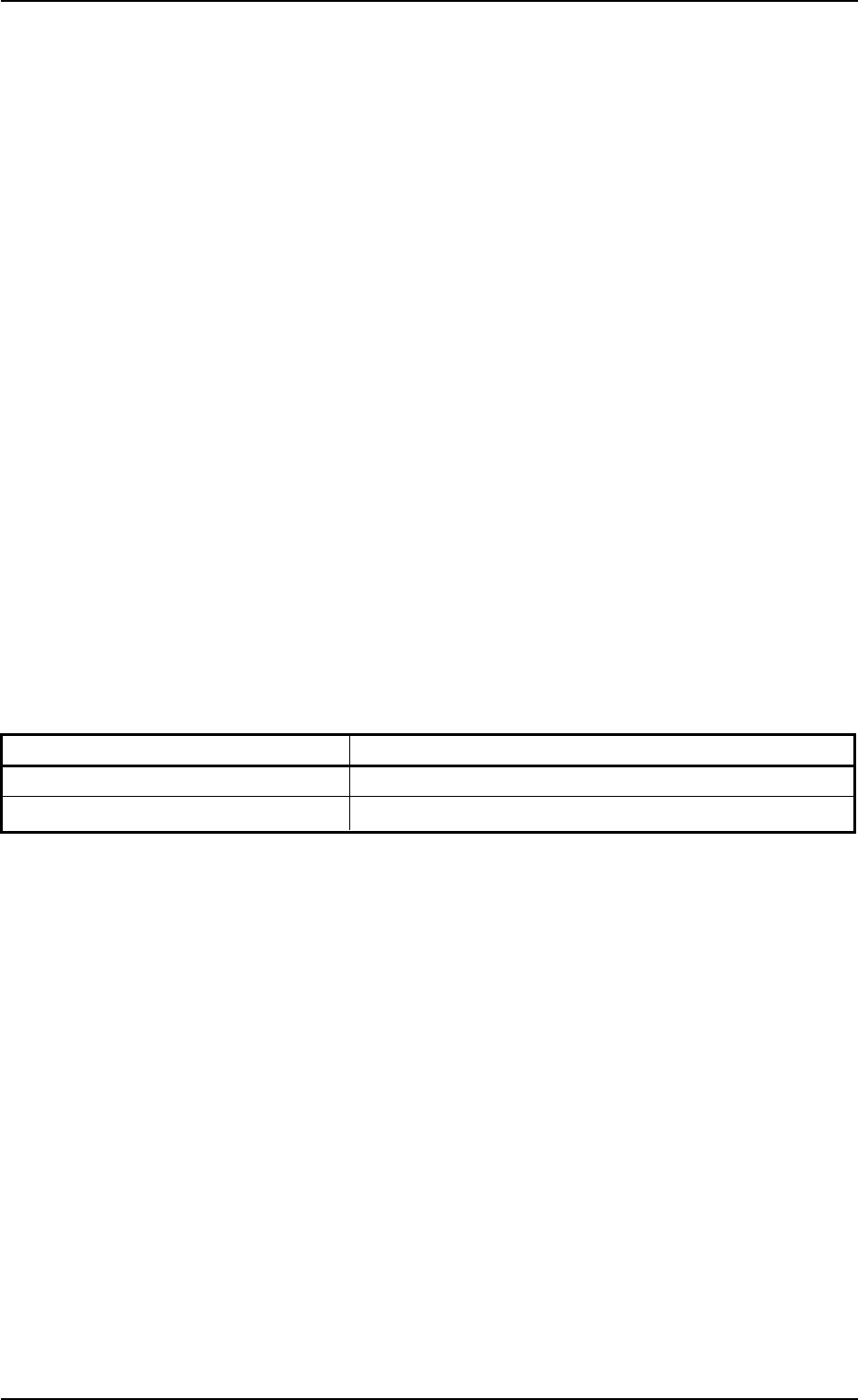
When "Disable" is set in the text box, the following tab sheet
appears.
Fig. 2B26 "Altn Fdr Mode (Disable)" Tab Sheet
Note

(3) Set "Enable" or "Disable" as the alternate feeder mode for each
individual feeders.
In the "Altn Fdr Mode (Enable)" tab sheet, it is possible to check how
the alternate feeder mode is working and to specify which feeders
are completed with component replenishment.
• As for the feeder No. where a component shortage error has been
detected, set "Enable" for the objective feeder No. after compo-
nent replenishment.
• Select the feeder No. for which "Enable" or "Disable" must be
changed and press the [Enable] or the [Disable] button.
• When the [Jump to Alt Fdr] button is pressed, the selected Nos.
are shifted to the destination alternate (substitute).
• When the [Enable All F1] button is pressed, "Enable" is set for all
the feeders on the selected feeder base (Feeder Base #1 in this
case).
• The set parameters ("Enable" or "Disable" (alternate feeder
modes) for each individual feeders) are saved when the [POWER
ON] or the [POWER OFF] button is pressed, the system is
cleared, or the current pattern program data is modified.
The parameters specified here become valid prior to the other
alternate-related ones that are designated in the pattern pro-
gram.
Even when "Enable" is set in the pattern program, this alternate
feeder mode (function) can be used to temporarily set "Dis-
able" in relation to preparation for the feeders.
2.13 Feeder Alternate Function
0206-001 2-24 AHB01ESPP
Note
2.14 Placement Coordinates Teaching Function
••
••
• P.C.B. Origin Offset Teaching
When the placement coordinates in the pattern program are shifted
overall in the X and Y directions, such overall deviations can be cor-
rected by changing the P.C.B. origin offsets X and Y in the operation
data.
This function can be used to calculate the amount of deviations semi-
automatically with the P.E.C. recognition camera and reflect the re-
sults as P.C.B. origin offsets X and Y for correction of the overall
deviations in the X and Y directions.
••
••
• Placement Coordinates Teaching
By capturing the image of P.C.B. patterns in the recognition window
with the P.E.C. recognition camera, it can be checked if wrong pa-
rameters are specified individually as placement coordinates in the
pattern program.
When a mistake is found, this function can be used to correct the
pattern program data, using the manual alignment function (match-
ing operation of displayed component outlines and P.C.B. patterns
with the pointing device).
Table 2B14
Step Reference
1. P.C.B. Origin Offset Teaching "5.3 "PCB Origin Offset Teach" Tab" in "Section 5"
2. Placement Coordinates Teaching "5.4 "Place Pos Teach" Tab" in "Section 5"
2.14 Placement Coordinates Teaching Function
0308-002 2-25 AHB01ESPP