2OM-1075-002.pdf - 第89页
3 . 4 P .C.B. Positioning The P .C.B.’s can be positioned, using the "P .C.B. T ransfer Adj" tab sheet of the "UNIT ADJ." window (submenu). Fig. 2C9 "P .C.B. T ransfer Adj" T ab Sheet Operat…

Operation Procedure
(1) Press the [All Device Overall Setup] button (*1).
(2) Enter the clearance data.
(3) When the [ENABLE] button on the operation panel is pressed in two
seconds after the [ON] button (*2) entitled "MOVE" in the "Control
Switch" group box, the all device overall setup operation is started
and the result appears in the "Status" text box (*3) for each device
as follows.
"Ready" : The setup operation is completed and the devices are
located at the position "P.C.B. Width + Clearance".
"Not Ready" : The devices are located at the position "P.C.B. Width
+ Clearance" but the current position is not under
control.
"---" : The current position or program is indefinite.
"---" (red) : "Disable" is set for the setup data.
(4) Confirm that "Ready" has appeared in the "Status" text box (*3) of
each device.
When "---" has appeared in the "Status" text box (*3), perform
the manual setup operation on the conveyor width.
Refer to "7.2.2" in "Section 5 Menus for Automatic Operation"
for the manual setup operation on the conveyor width.
0107-001 3-11
AHB01ESPP
3.3 Conveyor Width Adjustment
Note
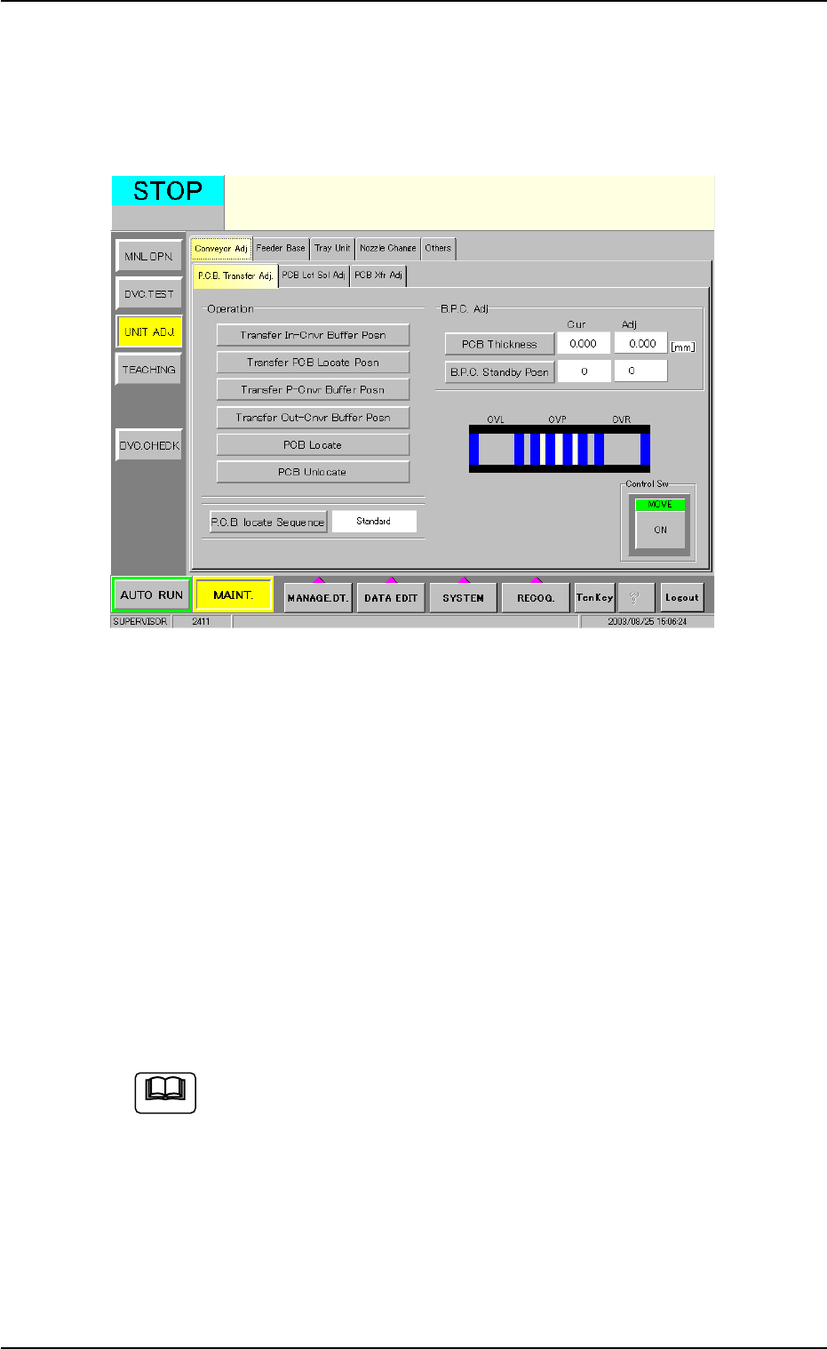
3.4 P.C.B. Positioning
The P.C.B.’s can be positioned, using the "P.C.B. Transfer Adj" tab sheet
of the "UNIT ADJ." window (submenu).
Fig. 2C9 "P.C.B. Transfer Adj" Tab Sheet
Operation Procedure
(1) Press the [PCB Thickness] button and enter a parameter as P.C.B.
thickness.
(2) Press the [B.P.C. Standby Posn] button and select a parameter as
P.C.B. standby position.
(3) Select the [Transfer PCB Locate Posn] button and press the [ON]
button (entitled "MOVE"). After that, press the [ENABLE] button on
the operation panel in two seconds.
(4) Select the [Move B.P.C. to PCB Locate Posn] button and press the
[ON] button (entitled "MOVE"). After that, press the [ENABLE] but-
ton on the operation panel in two seconds.
Refer to "4.1.1 "P.C.B. Transfer Adj" Tab" in "Section 6" for de-
tails.
3.4 P.C.B. Positioning
0308-004 3-12 AHB01ESPP
Note
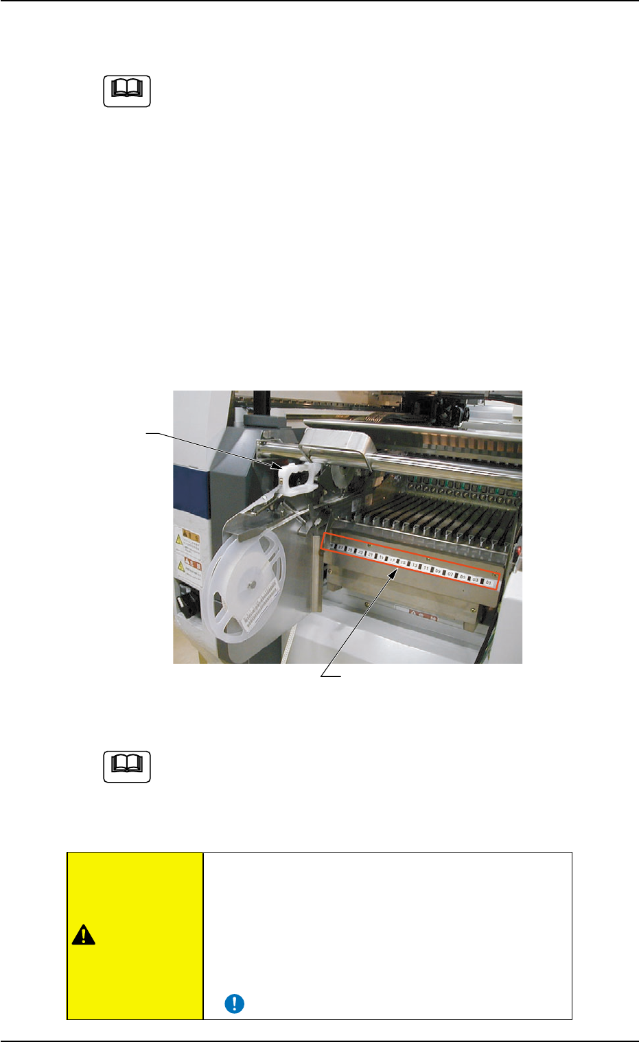
3.5 Preparation for Feeders
The following is explained, presuming that the tape feeders are
being used.
As for the preparation for the vibratory stick feeders and the
multi-layer tray feeders (option), refer to each instruction manual
for details.
Operation Procedure
(1) Refer to the placement feeder location data in the pattern program
and check the required tape feeders.
(2) Replenish each tape feeder with components.
(3) Detach the feeder base pullout prevention bar.
(4) Confirm which types of tape feeders (grip colors and types) should
be allocated to which feeder slot Nos. (Fdr. Nos.) before installing
the tape feeders.
Fig. 2C10
Refer to "Attachment and Detachment of Tape Feeders to Feeder
Base" in the instruction manual of tape feeders for details.
(5) Attach the feeder base pullout prevention bar.
• Install tape feeders correctly such that they are
seated securely. Otherwise, a collision with the head
section or a pick-up error will occur.
• Be sure to install the tape feeders on the correct
feeder slot Nos. (Fdr. No.). Otherwise, some
components may be trapped between the heads.
3.5 Preparation for Feeders
0308-004 3-13 AHB01ESPP
Fdr. No. Plate
Grip
CAUTION
Note
Note