2OM-1075-002.pdf - 第93页
(2) Component Recognition T est A recognition test can be performed to check whether or not the created component can be recognized normally . Operation Procedure (1) Select the component to be tested from the standard c…
3.7 All Clear Operation of Offset Data "Feeder B"
Operation Procedure
(1) Initialize the parameters in the "Feeder B" tab sheet (Offset Data) to
"0" (zero).
When a tape feeder is replaced according to a pro-
gram change operation, initialize the offset data "Feeder
B" to "0" (zero).
If the previous offset data "Feeder B" still remains, the
pickup position teaching function cannot be executed.
(a) The offset data "Feeder B" contains the offset data to cor-
rect the positional deviation in component pick-up positions
caused due to the variation in tape feeders.
Component recognition processing is performed during au-
tomatic operation to track the positional relation between
the nozzle and component centers. After that, the param-
eters (X and Y) are automatically updated for better pick-
up posture (pick-up at the component center).
(b) When "Disable" is set in the Auto Fdr. Axis Set" group box
in the "Opn. Mode" tab sheet of the "OPN. MODE" window
(submenu), the parameters are not automatically updated.
(c) Refer to ""Feeder B" Tab" in "Vol. 3: Programming and Ma-
chine Data" for how to delete the offset data "Feeder B".
3.8 Re-Verification of Component Library
(1) Pick-Up Location Teaching Function
The deviation of the component pick-up location can be corrected.
Refer to "5.1 "Pick-Up Location" Tab" in "Section 6" for the de-
tailed information on the pick-up locating teaching.
3.7 All Clear Operation of Offset Data "Feeder B"
0308-004 3-15 AHB01ESPP
CAUTION
Note
Note
(2) Component Recognition Test
A recognition test can be performed to check whether or not the
created component can be recognized normally.
Operation Procedure
(1) Select the component to be tested from the standard component
library and register it, using the test ID registration function.
• Specify the view size suitable for the compo-
nent.
If the suitable view size is not selected for the
component, the component may interfere with
the head section.
(2) Perform component recognition tests on the components picked
up from various feeders.
(3) When the component library data of the tested component is
changed, register it in the standard library, using the [Entry Comp
ID] button.
(4) Save the data in the network terminal (option).
Refer to "3.3 "Cmpnt Recog Test" Tab" in "Section 6" for a com-
ponent recognition test.
0308-004 3-16
AHB01ESPP
3.8 Re-Verification of Component Library
CAUTION
Note
4. Confirmation of Component Placement
4.1 Setting of Operation Mode
Before starting the automatic operation, press the [OPN. MODE] button
on the submenu bar. The "OPN. MODE" window opens. Confirm and
specify the following items related to the operation mode for the produc-
tion model.
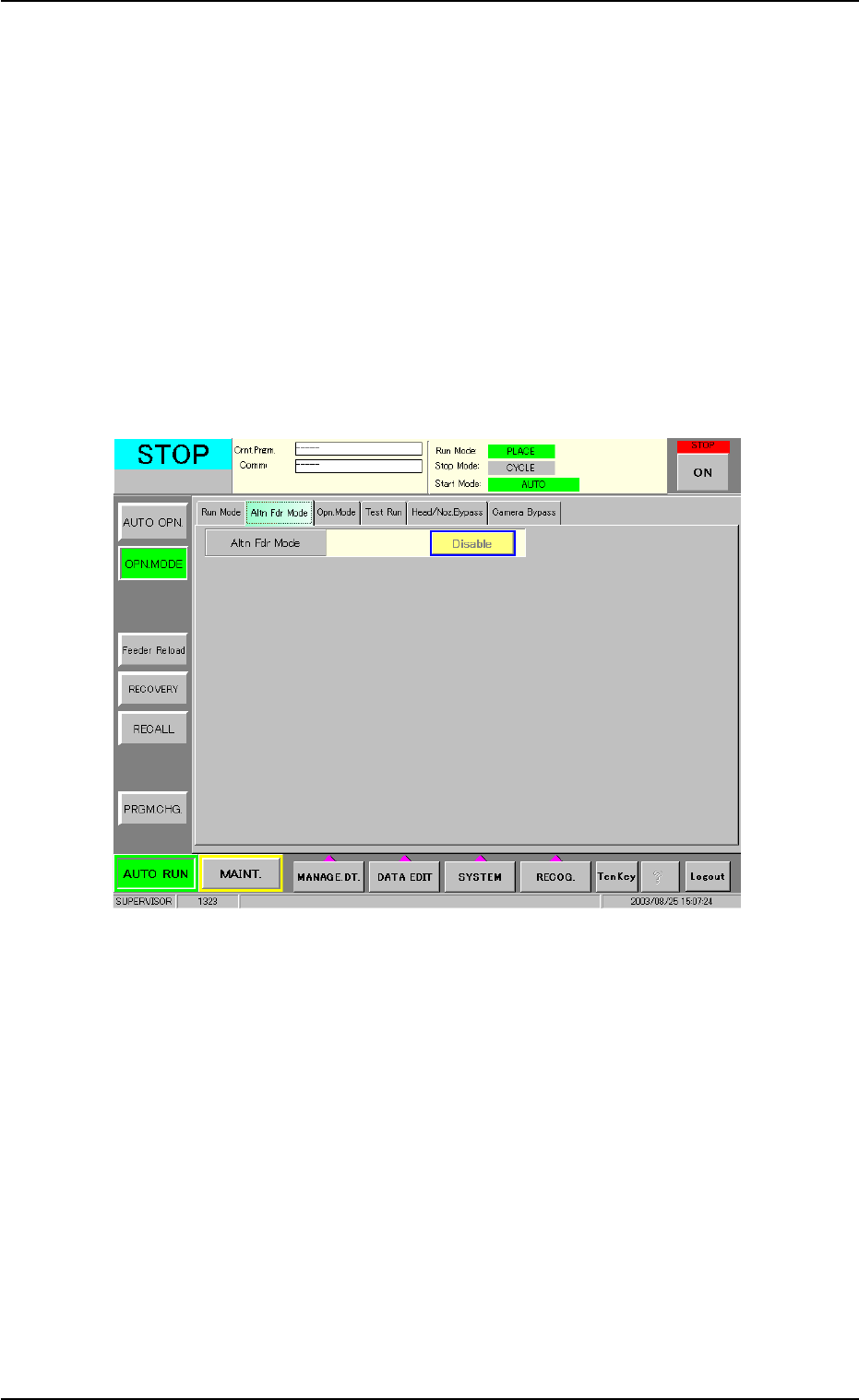
(1) Confirmation and Setting of Alternate Designation
Check the settings of the alternate function in the "Altn Fdr Mode"
tab sheet of the "OPN. MODE" submenu window.
Fig. 2C11 "Altn Fdr Mode" Tab Sheet
4. Confirmation of Component Placement
0308-004 3-17 AHB01ESPP