Nordson-EFD-Series-450-Instructions.pdf - 第5页
Series 450 Autovalve / Snuff Back | Instructions / Parts Lists 5 www.nordsonefd.com info@nordsonefd.com +1-401-431-7000 Sales and service of Nordson EFD dispensing systems are available worldwide. Maintenance (continued)…

Series 450 Autovalve / Snuff Back | Instructions / Parts Lists
4 www.nordsonefd.com info@nordsonefd.com +1-401-431-7000 Sales and service of Nordson EFD dispensing systems are available worldwide.
Maintenance
Two-component adhesives are messy and difficult to handle. It is important to note that routine maintenance must be
observed. If one delays maintenance until the valve stops, cleanup is very time consuming.
Routine Maintenance
1. Release pressures in A and B fluid hoses. Remove manifold and clean. We recommend overnight soaking in a suitable
solvent.
2. At the end of each shift, lubricate the back seals. We recommend auto grease. Pump auto grease through the grease
fitting (4) and out the plug (11). Using extra grease will extend seal life.
3. To clean the spool valves (75), first release the pressure on the A and B fluid hose. Then remove the manifold, and
advance the snuff-back adjustment (70) until the spool valves are protruding from the seat plate (8). With a toothbrush or
rag soaked in solvent, brush the spool valves clean. Protective eyeglasses should be used.
NOTE: With moisture sensitive urethanes or epoxies the spool valves must be cleaned. After cleaning, coat them spool
valves with auto grease.
4. The O-rings (6) and lip seals (3) are in a very harsh environment. In addition to resisting the adhesives, they must be inert
to the strong solvents used in cleaning the valve.
Installation
Connect Supply Lines
The A & B fluid hoses are connected to the side of the valve body (7), between the valve and the pumps, and should be as
short as possible. It is a good practice to install check valves in the hoses just before the valve.
For stationary mount, the air lines will be connected to the side of the air cylinder (1). Air to the front of the cylinder to close
and air to the back to open. If the optional handle is used, air is connected to the barbed fitting (105) on the side of the
handle.
The air line should have minimum pressure of 5.5bar (80psi).
Startup
With the hand-held model, start metering pumps and purge the air out of the A & B hoses and Autovalve. After the A and B
fluids come out of the manifold, attach a mixer to the manifold and hold the valve upside down with the mixer pointing up.
Dispensing A & B will purge the last pockets of air in the valve body.
A stationary mount or gantry installation requires a swivel mounting bracket. To complete purging, turn the valve with the
mixer pointing up and dispense A & B.
1. Take a ratio check by weight of A:B after the manifold. The Autovalve does No Metering. The Volume Ratio of A:B is
controlled by the metering pumps. However, between the metering pumps and the Autovalve are hoses. These hoses
will expand under pressure and cause lead-lag problems. Lead-lag refers to the uneven starting of the A fluid before the
B fluid. Nordson EFD offers 1:1 and wide ratio manifolds to reduce this problem. The selection of the correct manifold
depends on both the volume and viscosity ratio of A and B. Consult EFD Technical Services for details at 800-556-3484.
2. Adjust snuff-back screw (70) for minimum snuff-back. See page 12 of this manual for valve details.
Series 450 Autovalve / Snuff Back | Instructions / Parts Lists
5www.nordsonefd.com info@nordsonefd.com +1-401-431-7000 Sales and service of Nordson EFD dispensing systems are available worldwide.
Maintenance (continued)
The following options are available:
A. Chemical Compatibility with O-Rings
Usually the adhesives do not chemically attack the O-rings. However, during cleaning the valves are often immersed in
aggressive solvents. The following types of O-rings are available:
Type of O-Ring Color Recommended for Contact With...
Viton
®
Green or brown
• Methylene Chloride
• Alcohol
• Carbon Tetrachloride
EP Black
• MEK
• Ketones
• Acetone
PTFE Clear / orange
• All chemicals
• Encapsulated
B. Selection of Lip Seals
The lip seal consists of a U-cup with an interior O-ring. The following types of lip seals are available:
• Polyurethane U-cup with an interior Viton O-Ring. Good general purpose seal with good chemical and wear resistance.
U-cup colored orange with a brown Viton O-Ring. Recommended for filled abrasive adhesives.
• Viton U-cup with an interior Viton O-Ring. Good chemical resistance, but it is a soft seal with poor wear resistance.
U-cup colored black with brown O-Ring.
• UHMPE U-cup and an interior SS Spring. Excellent chemical and wear resistance. U-cup colored white with SS Spring.
Other combinations available upon request.
C. Chemical Compatability
The “A” or “B” resins can attack the seal material. An attacked seal will swell or become brittle in 3 to 14 days. If this occurs,
choose an alternate seal material. Listed below are the general guidelines.
For specific recommendations for Meter Mix Dispensing, contact our Technical Service Department at 800-556-3484.
Part #7702281 (Polyurethane)
Color: Orange
Epoxies — General
Polyurethanes
Polysulfides
Part #7702277 (UHMPE)
Color: White
Epoxies — Amine Catalyst
Polyesters
Acrylics
Series 450 Autovalve / Snuff Back | Instructions / Parts Lists
6 www.nordsonefd.com info@nordsonefd.com +1-401-431-7000 Sales and service of Nordson EFD dispensing systems are available worldwide.
Disassembly And Cleaning
1. Remove the manifold and seat plate (8). Pry bar slots are provided.
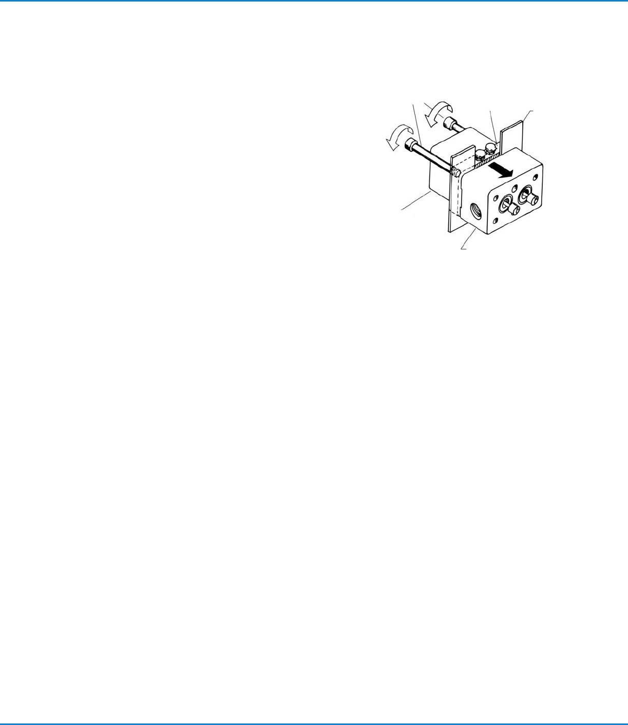
2. Remove the air cylinder bolts (2) and wiggle the air cylinder apart. If
the assembly is frozen, use the pry bar slots on the valve body (7) to
separate the valve body (7) from the tie plate (5). Insert flat pieces of
metal between the valve body and the tie plate as per Figure 1. Thread
the manifold screws (36) into the back of the tie plate and push the
valve body apart. Apply uniform pressure to prevent the body from
cocking and bending the spool valves (75).
3. Once apart, the parts should be cleaned. We recommend overnight
soaking in suitable solvent. All parts can be soaked except the handle
and air cylinder.
Rebuilding the Autovalve
1. After cleaning, inspect the following components:
a. Spool valves (75) for wear
b. Lip seals (3) — both outside and inside lip
c. Manually retract and extend spool valves from air cylinder (1).
d. If the optional handle is used, connect air into the inlet and check 4-way action of cartridge valve (103).
2. Lubricate lip seals (3) and shafts (75) with auto grease.
3. Insert four back lip seals (3): two into tie plate (5) and two into the valve body (7). The lip seals are two piece: an O-Ring
and U-cup. They should always be installed with the O-Ring facing the material inlets (body of the valve).
4. Insert two front lip seals (3) that are located in the seat plate (8). They should be installed with the O-Ring facing the back
of the valve (facing the air cylinder). Optional Installation: With O-Ring facing manifold. Used when minimum snuff-back
is required. However, reduced seal life can be expected.
5. Insert O-Rings (6) and assemble air cylinder (1) and valve body (7). and the valve body (7) and engage the screws (2).
6. Push seat plate (8) through spool valves (75) and tighten bolts (9).
Final QC Check
Before the manifold is assembled, we recommend the following procedure:
1. Check the open and close movement of the spool valves (75).
2. Check gap between seat plate (8) and spool valve (75). Refer to Figure 2 when spool valves are in open position.
3. Check front lip seals by pressurizing the valve body (7) and applying soapy water into the front seals. The valve body can
be pressurized by connecting air into the A and B inlet ports on the valve body.
4. Seat plate (8)
Manifold
screws
Tie plate
Metal
plate
Air cylinder
Valve body
Figure 1
Maintenance (continued)