00198045-01_OM_BulkFeeder_X_EN.pdf - 第45页
SIPLACE BulkFeede r X / Operating Ma nual 05/2017 Edition 45 Figure 5-10: Feeder details – Ca mera data In the Camera data t ab, details on the i nternal camer a are displayed.
SIPLACE BulkFeeder X / Operating Manual 05/2017 Edition
44
5.10 Component Test Functions with Internal Feeder Camera
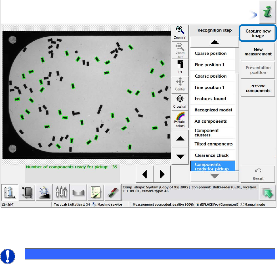
In the SIPLACE Vision live image tab, the current Vision image is displayed. A new image can be
taken by clicking on the Capture new image button.
Figure 5-9: Feeder details – Teaching dialog
The components can be taught in the corresponding teaching dialog for the feeder. Please refer to
the SIPLACE Vision online help for more information about the teaching process.
NOTICE
The Settings tab is only for settings during development.
SIPLACE BulkFeeder X / Operating Manual 05/2017 Edition
45
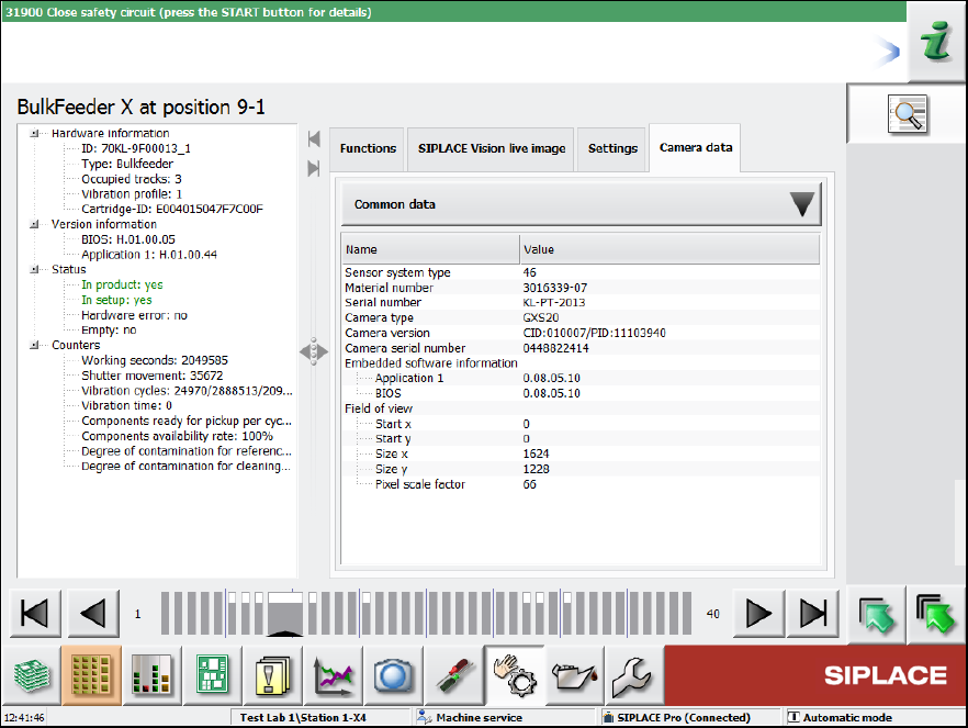
Figure 5-10: Feeder details – Camera data
In the Camera data tab, details on the internal camera are displayed.

SIPLACE BulkFeeder X / Operating Manual 05/2017 Edition
46
6 Troubleshooting
Two types of errors may occur when you are working with the SIPLACE BulkFeeder X:
– Hardware errors
– Process errors
Hardware errors are issued by the feeder and process errors by the station software. The
corresponding error messages are listed below.
Generally, the status display LED on the Base Unit lights up red if an error occurs.
6.1 Hardware Error Messages
Hardware errors are displayed on the 7-segment display of the control panel as:
Er/Error no (e.g. Er/01 for error number 01).
The following error messages may be displayed.
Error no. Error description Correction
01 Locking mechanism is still outside after
power ON and initialization
Push in locking mechanism
02 Booting has been stopped during
initialization as an unsupported version
of a hardware module has been
detected
Hardware configuration error (not possible
at customer site)
03 Saving runtime data to the flash did not
succeed
Hardware error => send to manufacturer
for repair
07 The CAN controller is in error state BUS
OFF
Switch the machine off and on; check the
light conductor in EDIF
08 Max. processor temperature has been
exceeded
Hardware error => send to manufacturer
for repair
09 Data flash of the processor is defective Hardware error => send to manufacturer
for repair
11 Cartridge is not inserted correctly Check whether the Cartridge is inserted
correctly or removed from the Base Unit
12 Cartridge identification could not be read Hardware error
17 Max. vibration actuator temperature
exceeded (calculated in eSW)
(Should not occur in regular placement
mode)
18 Max. coil driver temperature has been
exceeded
Hardware error => send to manufacturer
for repair
19 Acceleration sensor on cube has
detected a shock
Not used so far
25 Plate shutter or container locking control
timeout (eSW error)
Hardware error => send to manufacturer
for repair