00191017-01.pdf - 第179页
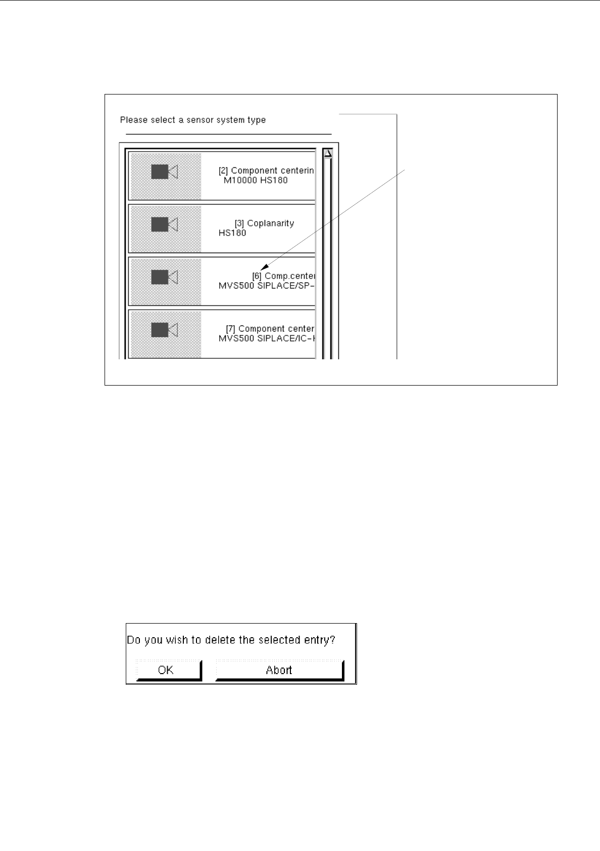
User’s Manual Line Computer UNIX 6 Product / Package Form Software Version 403.xx Edition 06/97 6.1 Package Form Editor 6 - 19 Fig. 6.1.7 Selection Window of the "Sens or T ype" ● Clic k on de sire d type . The…
6 Product / Package Form User’s Manual Line Computer UNIX
6.1 Package Form Editor Software Version 403.xx Edition 06/97
6 - 18
6.1.2.8 Package Form Editor Command Area - "Handling data" Display
In the command area (see Fig. 6.1.4) two different tools can be selected from (nozzle or sensor type) that can
be created or deleted by means of the corresponding commands. The desired tool type desired is selected by
clicking on the button adjacent to its name.
COMMANDS
The procedures to be followed for the execution of the commands are described in the following.
-
Create
This command can be used to create the nozzles and sensor system types required for the current
package form.
●
Activate the button of the desired tool type.
●
Click on Create.
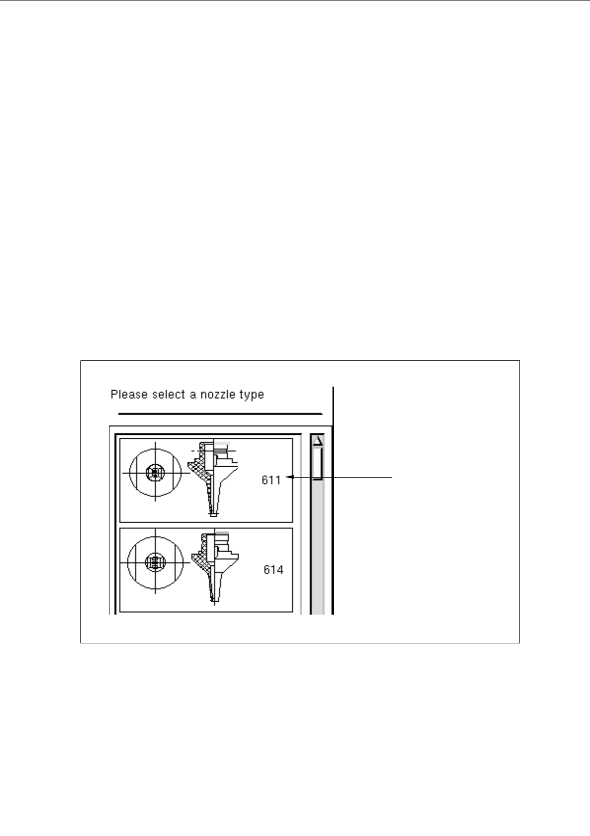
The selection window containing a list of all defined types of the selected tool type is opened.
Fig. 6.1.6 Selection Window of the "Nozzle Type"
nozzle type
User’s Manual Line Computer UNIX 6 Product / Package Form
Software Version 403.xx Edition 06/97 6.1 Package Form Editor
6 - 19
Fig. 6.1.7 Selection Window of the "Sensor Type"
●
Click on desired type.
The selection window is closed. The symbol of the selected tool type together with the number of
the created tool type is displayed in the display area of the main window.
-
Deleting
An existing tool can be deleted.
●
Click on button of the desired tool type.
All existing tools of the selected type are displayed.
●
Select tool from the display area.
●
Click on
Delete
.
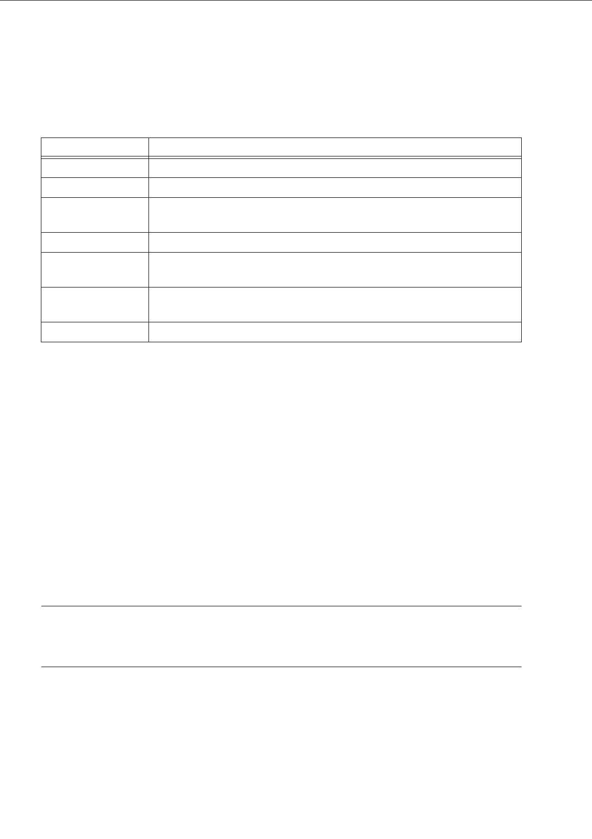
The following dialog box is opened.
●
Click on
OK
in the dialog box.
The dialog box is closed.
The symbol of the selected tool is no longer displayed in the display area.
number of the
sensor system type
6 Product / Package Form User’s Manual Line Computer UNIX
6.1 Package Form Editor Software Version 403.xx Edition 06/97
6 - 20
Nozzle Types
The table below lists all nozzle types suitable for the different machine types and head types.
The
first digit
in the nozzle type designation refers to the machine and head type on which the nozzle will be
used.
The
second digit
normally refers to the nozzle material. However, this digit may also indicate whether the
nozzle is of a special type:
0 = steel,
1 = plastic,
2 ... 9 = etc.
The number "9" is used for freely programmable special nozzles.
The
last digit
refers to the nozzle size: 1 = smallest nozzle
For SIPLACE-only applications, only nozzle types 3xx, 4xx, 6xx, 7xx and 8xx are relevant. An adapter allows
type 2xx nozzles also to be used on IC heads.
NOTE
A detailed overview of the current standard nozzles is contained in chapter 17 of the User’s Manual
"SIPLACE 80S-20/F
4
", edition 07/97.
Nozzle type Machine type and head type
1xx HS-180 without nozzle changer
2xx HS-180 with nozzle changer
3xx SP-120, SIPLACE 80S-15/F3 for revolver head featuring old segments (version 1)
that cannot be used with a nozzle changer
4xx SIPLACE 80F3/F
4
, IC head
6xx (5xx) SIPLACE 80-S15/F3 for revolver head featuring the new segment version (version
2) that is suitable for use with nozzle changers
7xx 12-nozzle revolver head SIPLACE 80F
4
and SIPLACE 80S-20,
6-nozzle revolver head SIPLACE 80F
4
-6
8xx 6-nozzle revolver head SIPLACE 80F
4
-6
Tab. 6.1 - 1 Nozzle Types (sorted in accordance with machine and head types)