00191017-01.pdf - 第223页
User’s Manual Line Computer UNIX 8 Product / PCB Software Version 403.xx Edition 06/97 8.1 PCB Editor 8 - 11 Fig. 8.1.5 Examples "Usage and Results of some Comm ands in the Str ucture Editor" NO TE per taining …
8 Product / PCB User’s Manual Line Computer UNIX
8.1 PCB Editor Software Version 403.xx Edition 06/97
8 - 10
-
Call up the
Cluster Editor
for the definition of the cluster data (only possible in the Structure Mode)
●
Activate icon in the command area.
●
In the display area select partial PCB structure with a mouse-click.
●
Select
SERVICES
-->
Cluster Editor
The window of the Cluster Editor (see Fig. 8.1.8) is opened.
-
Structure Mode
This menu option serves to switch the view area from the Graphic Mode to the Structure Mode.
●
Select
SERVICES
-->
Struct. mode
The view area is switched to the Structure Mode (see Fig. 8.1.4).
-
Graphic Mode
This menu option serves to switch the view area from the Structure Mode to the Graphic Mode.
●
Select
SERVICES
-->
Graph. mode
The view area is switched to the Graphic Mode (see Fig. 8.1.6).
-
Call up the
Structure Editor
for the processing of a new PCB
●
Activate icon in the command area.
●
Select
SERVICES
-->
Structure Editor...
.
The FSB for the selection of a new PCB is opened (see page 8 - 6).
●
Select PCB and confirm with
OK
.
The structure of the selected PCB is displayed in the display area of the new window.
Or (to obtain an empty window for a new PCB):
●
Enter new name.
The window of the Structure Editor is opened under the name of the new PCB.
8.1.3.3 Command Area of the Structure Editor (Structure Mode)
The commands are symbolized by means of icons. If an icon is activated by clicking upon it, the respective
action can be performed on a partial PCB structure subsequently to be selected.
On opening the Structure Editor, the "Select" command is automatically active.
(The arrow in the icon points from the bottom left to the top right).
NOTE
The procedures and results of some of the commands described in the following are shown as examples
in Fig. 8.1.5 where the numbers 1 or 2 indicated in the circles represent the sequence of the steps to be
performed; the structures represented as broken lines stand for the results.
User’s Manual Line Computer UNIX 8 Product / PCB
Software Version 403.xx Edition 06/97 8.1 PCB Editor
8 - 11
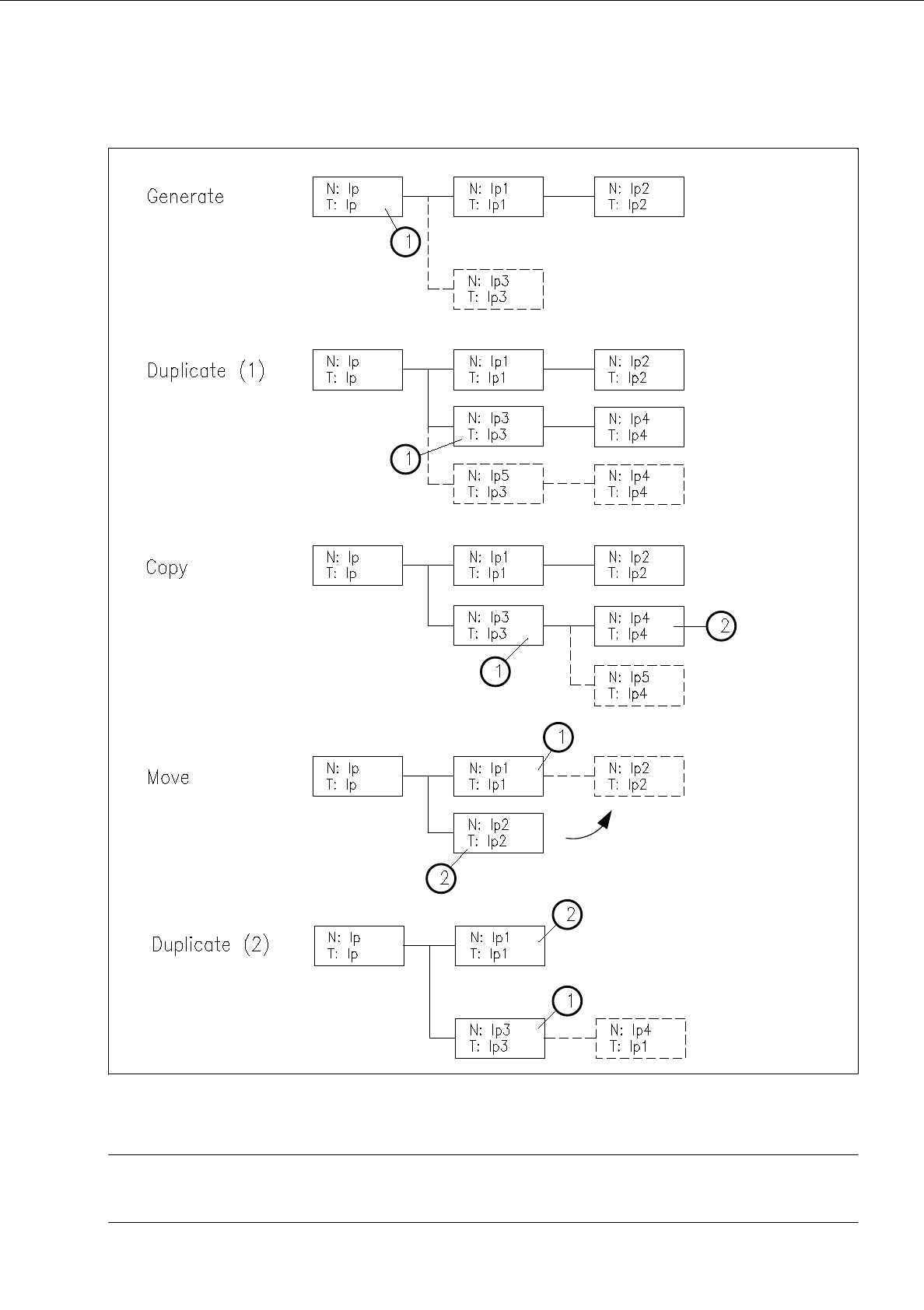
Fig. 8.1.5 Examples "Usage and Results of some Commands in the Structure Editor"
NOTE pertaining to Fig. 8.1.5
"Duplicating (1)" is described on page 8 - 12 and "Duplicating (2)" on page 8 - 14.
8 Product / PCB User’s Manual Line Computer UNIX
8.1 PCB Editor Software Version 403.xx Edition 06/97
8 - 12
-
Selection
If this icon is active (displayed in reverse video, with the arrow pointing from the bottom left to the top
right), the PP or NU-Editor can be called up for the selected partial PCB structure. If the topmost par-
tial PCB structure is selected, the current PCB can be duplicated using the "Copy PCB" menu
function.
●
Activate icon .
●
The partial structure selected is highlighted in light green. All partial structures linked to it are
highlighted in dark green.
●
Select desired menu function (e.g. SERVICES --> NU-Editor...).
-
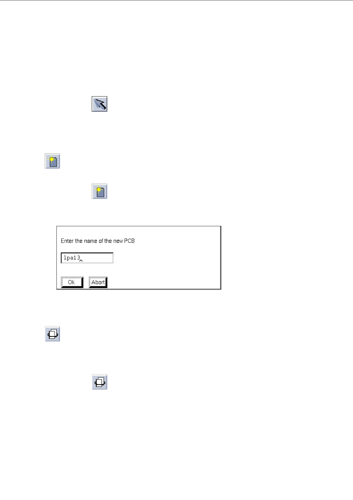
Generating
a new partial PCB structure with the corresponding new PCB type
This command serves to generate a new partial structure with a cross-reference to a new PCB type.
●
Activate icon .
●
Select PCB type.
The following dialog box for entering the name is displayed.
●
Enter the name and confirm with
OK
.
The new PCB type is appended to the selected one and displayed in the display area.
-
Duplicating
a partial PCB structure
Existing cross-references to a given PCB type can be duplicated from a PCB partial structure thus
generating a new partial structure. Except for the coordinates, the data of the duplicated partial PCB
structure are identical.
●
Activate icon .
●
Select partial PCB structure.
The dialog box for entering the name is displayed.
●
Enter the name and confirm with
OK
.