00191017-01.pdf - 第239页
User’s Manual Line Computer UNIX 8 Product / PCB Software Version 403.xx Edition 06/97 8.1 PCB Editor 8 - 27 8.1. 4.1 E DIT Menu - Resetting Cluster Data The en trie s alrea dy e xisti ng f or the P CB ty pe conce rn ed …

8 Product / PCB User’s Manual Line Computer UNIX
8.1 PCB Editor Software Version 403.xx Edition 06/97
8 - 26
Menu Bar
The menu bar contains the menus "FILE", EDIT", "SERVICES" and "HELP".
A detailed description of the "EDIT" menu is contained in section 8.1.4.1 and a description of the "SERVICES"
menu is contained in section 8.1.4.2.
NOTE
Since the functions and operation of the "FILE" and "HELP" menus are similar to those in other application
programs of the line computer, they are described comprehensively in chapt. 2.
Editing area
(see section 8.1.4.3)
All PCB-specific data that are required for the description of a PCB, the so-called cluster, are entered in this area.
-
The cluster description contains the following data:
-
Dimensions of the PCB such as length, width and height
-
Process data for the production of the PCB, such as PP position recognition on/off, ink spot recogni-
tion on/off, PCB position recognition on/off, placement on/off (omit cluster) and the max. component
height tolerance for the coplanarity measurement
-
Fiducial sets and fiducials
Setting area
(see section 8.1.4.4)
The operational sequence of the placement process can be defined in this area by activating/deactivating the
respective buttons (e.g. assembly with or without PCB position recognition).
"Edit fiducials" command button
The window of the Fiducial Editor is opened by clicking on this button (see Fig. 8.1.10).
User’s Manual Line Computer UNIX 8 Product / PCB
Software Version 403.xx Edition 06/97 8.1 PCB Editor
8 - 27
8.1.4.1 EDIT Menu
-
Resetting Cluster Data
The entries already existing for the PCB type concerned can be deleted from the editing area.
●
Click on EDIT --> Reset cluster data.
The editing area is empty, new entries can be made.
NOTE
If the PCB Editor is exited from without activating "Save", the old data will be redisplayed when the
PCB(Cluster) Editor is called up again.
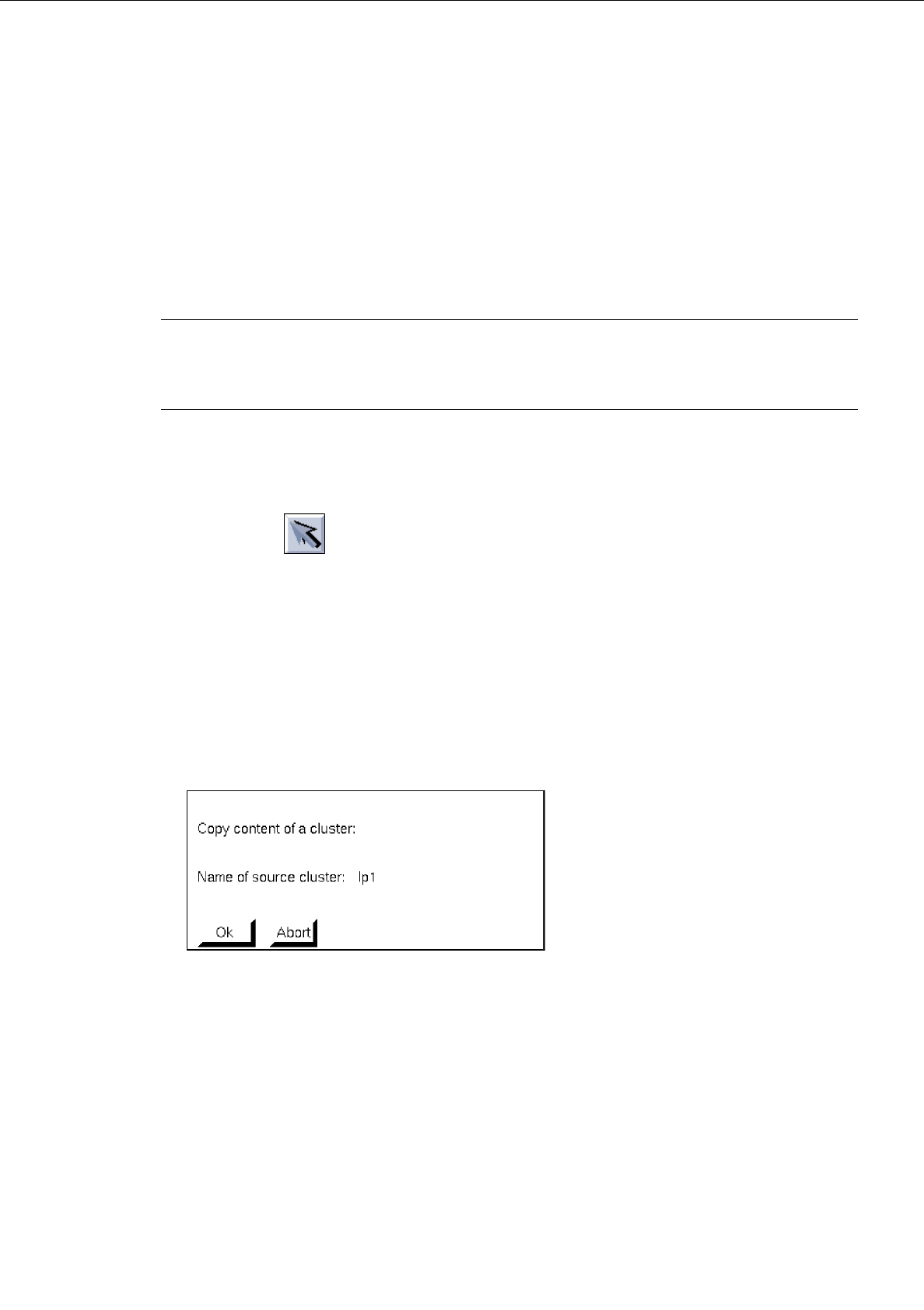
-
Loading cluster data from
This function enables the cluster data of another PCB type (single circuit) to be loaded into the
Cluster Editor of the current PCB type.
●
Activate icon in the command area of the current Structure Editor.
●
Select partial PCB structure (target).
●
Click on SERVICES --> Cluster Editor.
The FSB for the selection of the (source) PCB is opened (see page 8 - 6).
●
Select PCB by double-clicking.
The main window of the new Structure Editor is opened.
●
Click on the partial PCB structure from which the cluster data are to be loaded (source).
●
Click on EDIT -> Load cluster data from in the current Cluster Editor (target).
The following dialog box appears:
●
Click on OK if the action is to be performed.
The window of the Placement Position Editor is displayed for checking purposes.
●
Click on window of Cluster Editor (to make it the topmost window of the window batch).
The cluster data loaded are now displayed.
8 Product / PCB User’s Manual Line Computer UNIX
8.1 PCB Editor Software Version 403.xx Edition 06/97
8 - 28
8.1.4.2 SERVICES Menu
-
Opening the Placement Position Editor
●
Click on SERVICES --> Placement Position Editor.
The window of the Placement Position Editor is opened (see section 8.1.6).
-
Opening new Structure Editor
●
Click on SERVICES --> Structure Editor... .
The FSB for the selection of a new PCB is opened (see page 8 - 6).
●
Select PCB and confirm with OK.
The structure of the selected PCB is displayed in the display area of the newly opened window.
8.1.4.3 Editing Area of Cluster Editor
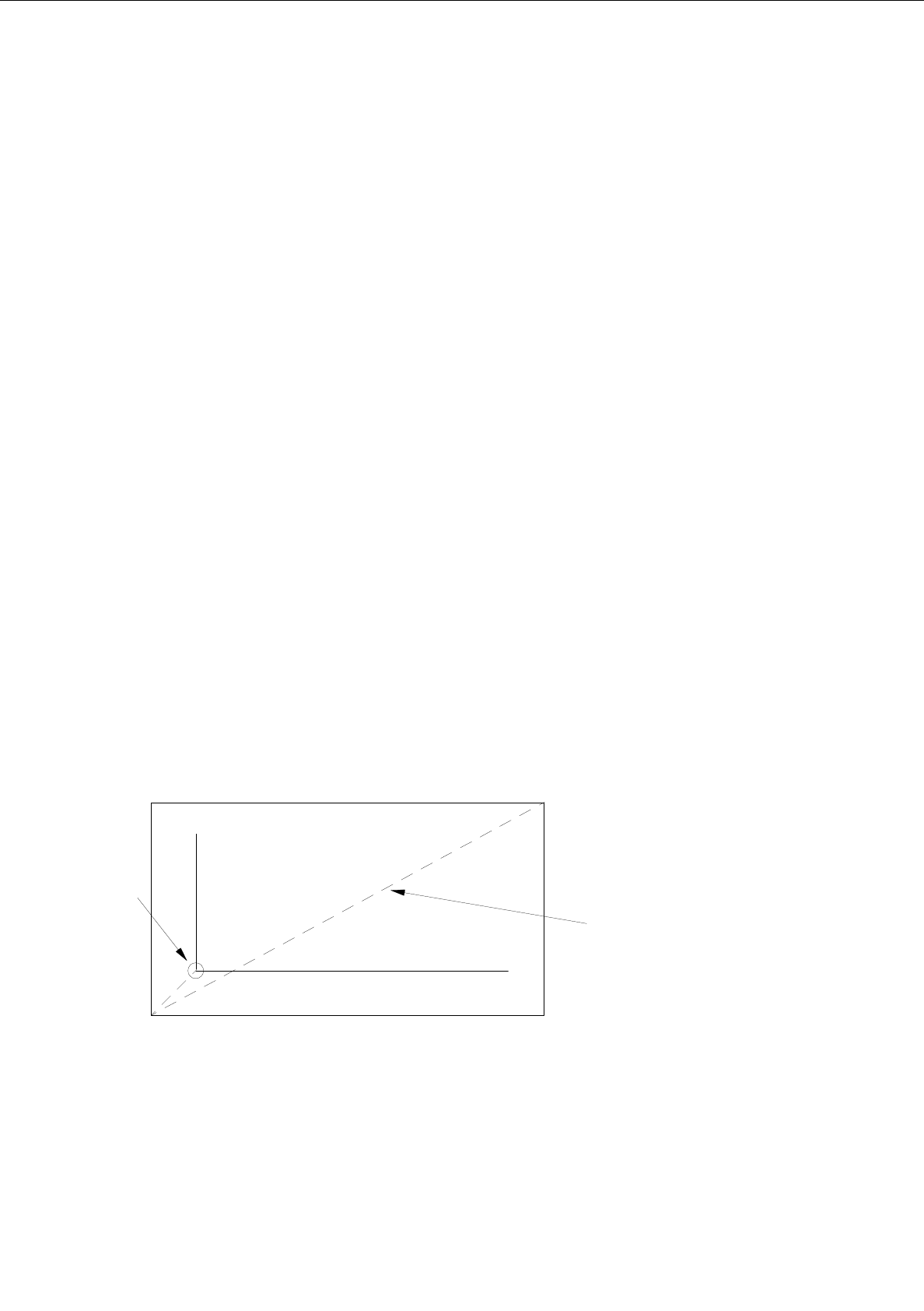
INPUT POSSIBILITIES
The outer measurements of the current PCB type (cluster) are defined by the dimensional values in x and
y-directions. Values up to max. 999.999 can be entered in each case.
-
Vector (0,0)-->corner_1 X [mm] or Y [mm]
example: X = -10.000; Y = -10.000
-
Vector corner_1-->corner_2 X [mm] or Y [mm]
example: X = 80.000; Y = 50.000
-
PCB height: h [mm]
In this field the PCB thickness is to be entered; it is possible to
enter a number with three places before and after the decimal
point.
+ Y
+ X
corner 1
corner 2
vector
0, 0