7OM-1603-006_w - 第111页
7OM-1603 3-6 Chapter 3 : 1. Maintenance Menu 1.2.2.1 Elevator Height and Inclination Adjustment Procedures • T ools to be used : T wo Hook Spanners (Maintenance T ool Accessory) Procedure (1) Fix the traverse cart sectio…

7OM-1603
Chapter 3 : 1. Maintenance Menu
3-5
1.2.2 Detachment Procedure of Multi-Layer Tray
Procedure
(1) Select the tray unit to be changed in the "Unit select" section box in the "Unit
Chg." menu.
(2) Press the [Tray Removal Order] button in the "Change Order Guidance"
section.
(When any component is left on the tray unit, such component is removed.)
(3) Press the [Fdr READY] switch turn ON the power to the multi-layer tray
feeder.
(4) Press the [Zero] button.
(The motor shaft for the multi-layer tray feeder will be "zeroed").
(5) Release the foot receiving pans of the elevator unit.
(6) Release the clamp of the elevator unit.
(7) Remove the elevator unit from the traverse cart and disconnect the bundled
connector for the elevator unit and the air connection plug from the cart.
(8) Press the [Fdr READY] switch for some while to remove the cart.
(9) Disconnect the traverse cart connecting bundled connector from the main
machine.
1007-003
7OM-1603
3-6
Chapter 3 : 1. Maintenance Menu
1.2.2.1 Elevator Height and Inclination Adjustment Procedures
•
Tools to be used
: Two Hook Spanners (Maintenance Tool Accessory)
Procedure
(1) Fix the traverse cart section onto the main machine installation section.
(2) Move the elevator unit to the attachment position.
(3) Adjust the elevator unit caster height to satisfy the following conditions.
(The bolt pitch in the caster section should be 3 mm / pitch).
•
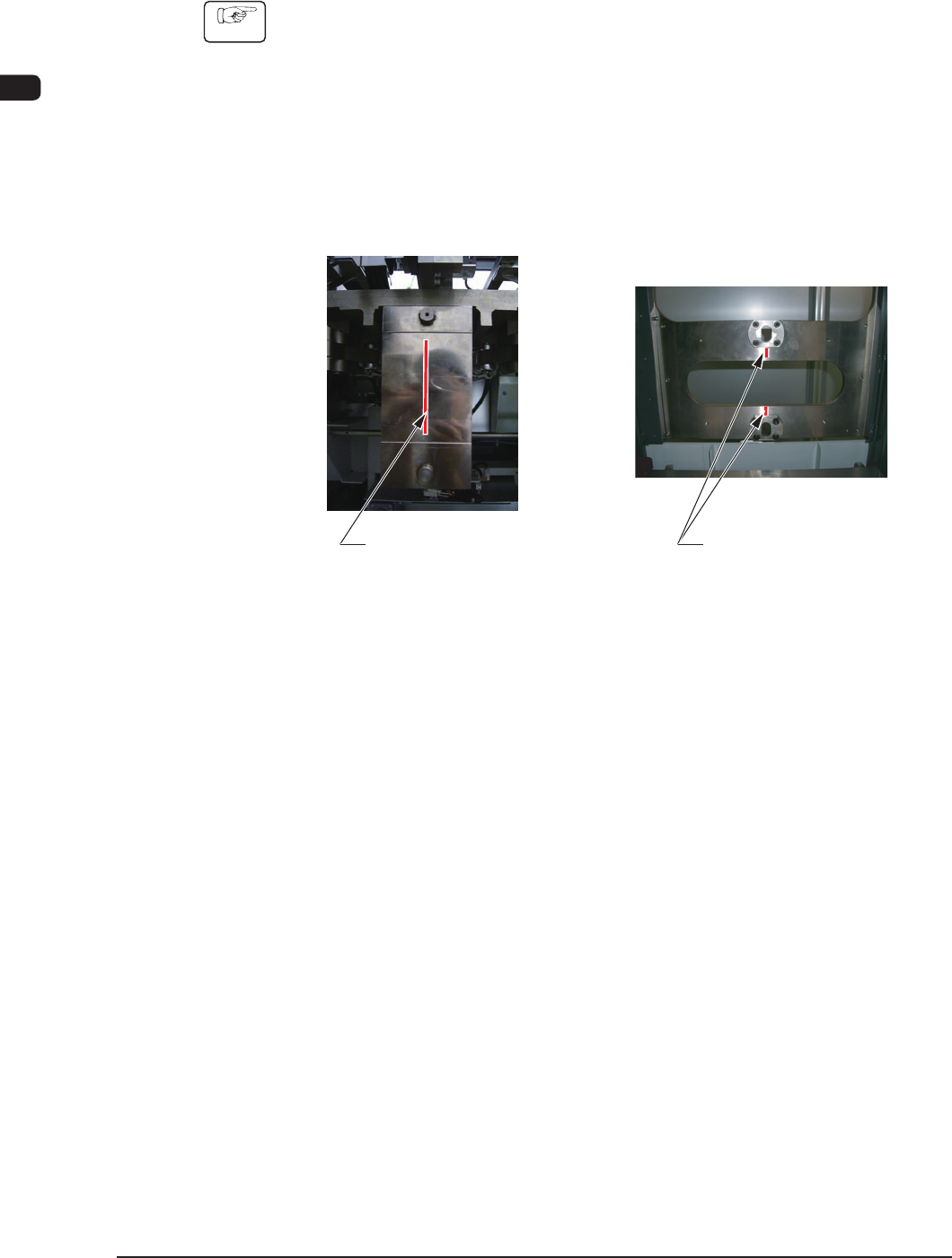
The pilot pin on the side of the traverse cart should be located at the center
of the long hole section on the elevator side.
Positioning Pin on
the Traverse Cart Side
Long Hole Section on
the Elevator Side
Marking-off Line
on the Traverse Side
Marking-off Line
on the Elevator Side
F7C5
1003-002
7OM-1603
Chapter 3 : 1. Maintenance Menu
3-7
•
The marking-off on the unit on the traverse cart side should agree with
that on the elevator unit side.
Combined view of the units
on the elevator side
and traverse cart side
F7C6
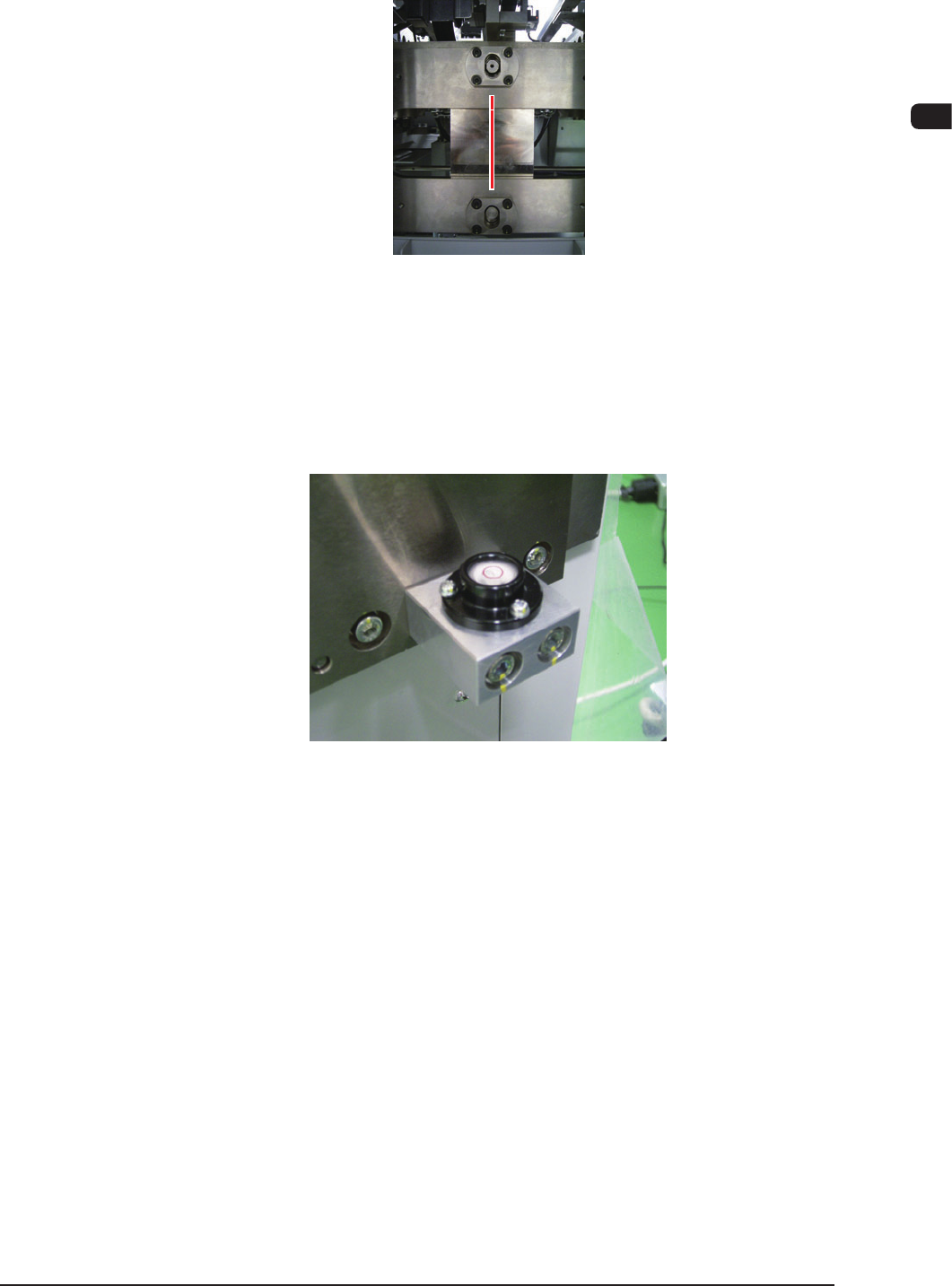
•
The air bubble in each of the two levels on the rear side of the elevator
unit should be static within the center red circle.
Level (2 locations)
F7C7
(4) Fix the bolt in the caster section using the lock nut.
1007-002