7OM-1603-006_w - 第179页
7OM-1603 5-14 4.2 Electrical Circuit Diagrams Multi-Layer T ray Block Diagrams 4.2 Electrical Circuit Diagrams Multi-Layer T ray Block Diagrams 0908-001 A(M921W A---0001) UA54 UA54 UB76 UB74 Traverse Shaft (ID:2) Elevato…
7OM-1603
5-13
0908-001
7OM-1603
5-14
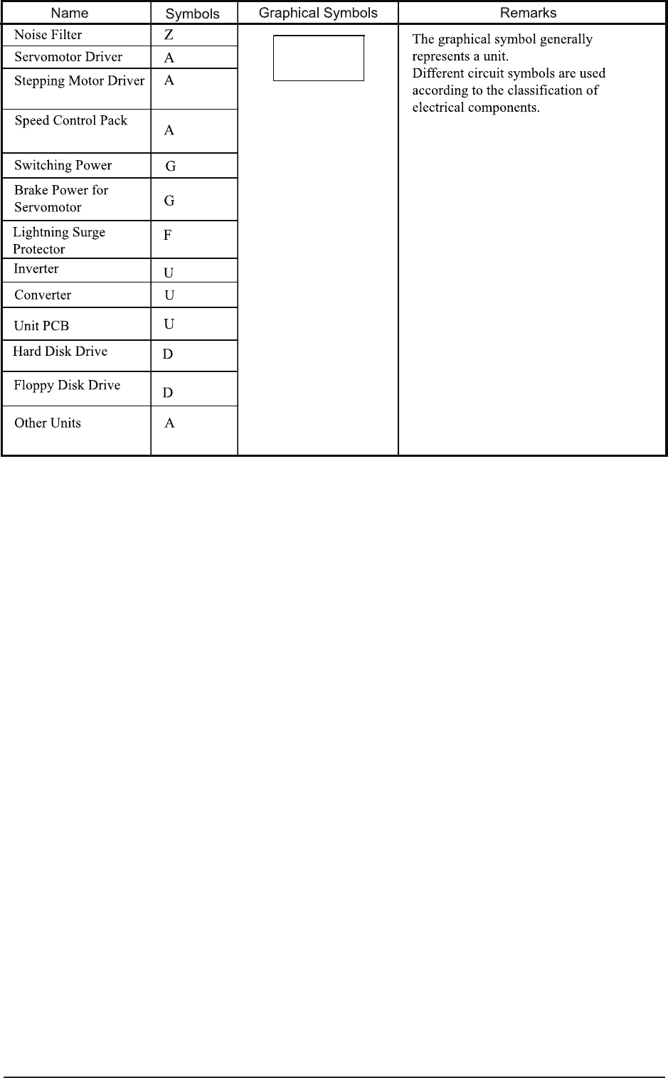
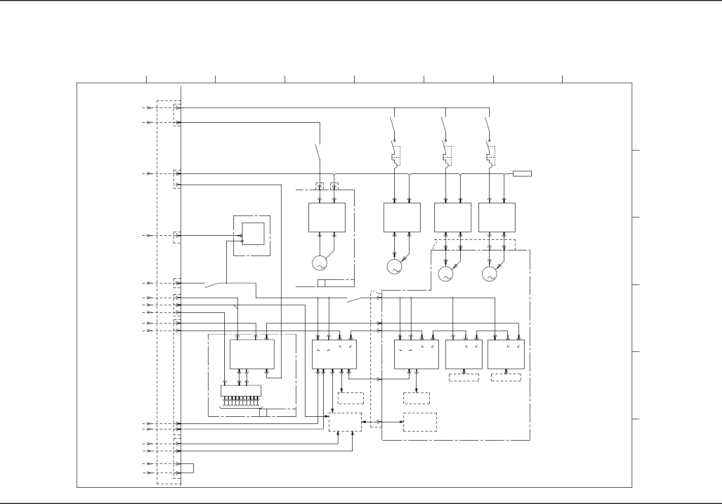
4.2 Electrical Circuit Diagrams
Multi-Layer Tray Block Diagrams
4.2 Electrical Circuit Diagrams Multi-Layer Tray Block Diagrams
0908-001 A(M921WA---0001)
UA54 UA54UB76
UB74
Traverse Shaft (ID:2)
Elevator Shaft 1 (ID:3) Elevator Shaft 2 (ID:4)
Cutter Shaft (ID:1)
UB26UB26
3 Pin
2 Pin
3 Pin
2 Pin
2 Pin
4 Pin
5 Pin
5 Pin
5 Pin
6 Pin
3
M
3
M
3
M
3
M
U155U154
ILB-TR
CN1 CN2CN3 CN4CN6 CN2
U69
FB
U68
CN100
SV-NET
【Main Machine Side】
Tape Feeder I/O Lane U
X300E
Each Relay and
Safety Circuit
【Traverse】
K101 K201
Q101 Q201K52
A01
CN1 CN2
A02
CN1 CN2
A03
CN1 CN2
A63
CN1 CN2
M63
M01
CN3 CN5
M02 M03
U157
SW2
CN1 CN2A CN2B
U156
SW1
CN1 CN2A CN2B
K301
X300D
Multi-layer Tray Connection Check
HLS
24A2
24G1
24G2
24G5,6
Main Machine Emergency Stop Detection
Main Machine Safety Relay
CN9CN8 CN1
SW PCB SW PCB
X300B
X300C
Offline control
Safety Switch
CN3 CN5 CN3 CN5CN3 CN5
ILB-EV
DC48V
AC200V
CN3 CN4
RS232C
X300F
Sensor and
Load
Sensor and
Load
N.C
X30
X16301
【OP】
CU-SRS
U
CT TV EV1 EV2
X16302
FB-SRS
U
HLS HLSHLSHLS
HLS SensorLoad
PWR
SensorLoad
PWR
K505
Q301
Bundled Connector
TV-EV
PWR RS232C
PWR PWR
Bundled
Connector
TV-EV
External Unit Connecting
Bundled Connector
24B11
X300D
RS232C
(Specially Designed for ACV)
ID Controller
X4
Power
【OP】
Interlock Signal
(To Main Machine ILB)
24B1
X300D
K52
24B10
【Elevator】
Terminal
Resistance
1 2 3 4 5 6 7 8
A
B
C
D
E
F
1 Pin
1 Pin
1 Pin
1 Pin
1 Pin
2 Pin
7OM-1603
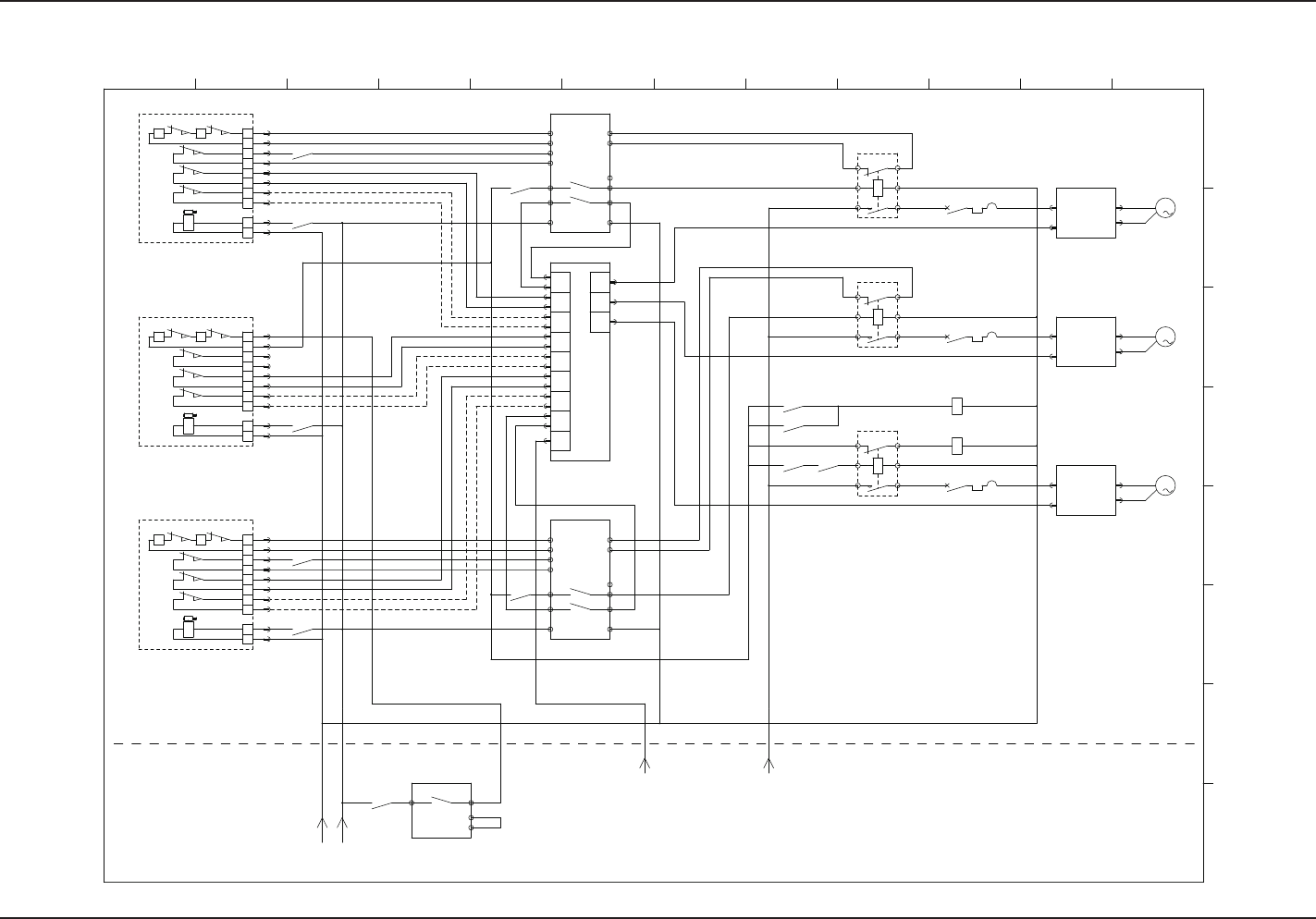
5-15
4.2 Electrical Circuit Diagrams Multi-Layer Tray Safety Circuits Block Diagrams
Multi-Layer Tray Safety Circuits Block Diagrams
0908-001 -(M921WA---0002)
3
M
3
M
3
M
S0501(Lower)
51
52
A1
A2
Power To Lock
S0503(Magazine)
11
42
21
22
51
52
A1
A2
31
32
Power To Lock
1241
K301
CN1 CN3
CN5
M03
S0502(Upper)
51
52
A1
A2
Power To Lock
T11
T12
T21
T22
K201
CN1 CN3
CN5
M02
Q101
CN1 CN3
CN5
M01
K002
T31
T32
Q201
2423
K508
K509
K507
1413
A1
T11
T12
T21
T22
K001
T31
T32
2423
1413
A1
A2
K503
K502
K3
1413
T31
T32
K22
24A2
Input
Input
Input
Input
Input
Input
A2
Input
Input
10A
421
Emergency Stop Detection
CN7
CN7
CN7
AC200V(Single-Phase)
Input
Output
Output
Output
Main Machine Side
Multi-layer Tray
K101
Q301
11
42
21
22
31
32
1241
11
42
21
22
31
32
1241
K512
K513
K513
K513
K512
K508
K507
K504
Safety Switch
Rock Contact
Safety Switch
Open/Close Contact
Open/Close Contact
Open/Close Contact
Rock Contact
Rock Contact
EV2 Main Power ON
EV2(Upper)
A03
Safety Switch
Rock Contact
EV1 Main Power ON
EV1(Lower)
A02
TV
A01
Safety Relay
Check the Solvent
I/O PCB
Safety Relay
Safety Relay
Check the Solvent
Check the Solvent
*The welding check for TV or EV is performed on the multi-layer tray side.
TV Main Power ON
Open/Close Contact
Open/Close Contact
Open/Close Contact
Rock Contact
Open/Close Contact
Open/Close Contact
Open/Close Contact
Rock Contact
For Check the Solvent
For Check the Solvent
1
2 3 4 5 6 7 8 9 10 11 12
A
B
C
D
E
F
G
H