1OM-1625-004_w.pdf - 第109页
1OM-1603 2-8 2. Operation Screen : Chap.2 1012-003 2.1 Control Menu When the [Control] button is pressed on the common menu bar, the "Control menu" window appears. In the "Cont rol menu" window, group…
1OM-1603
2-7
2. Operation Screen : Chap.2
1012-003
[Control] Button
When pressed, this button opens the "Control" window.
Reference
Refer to "2.1 Control Menu" for the detailed information on the "Control"
window.
[ChngScrn] Button
When this button is pressed, the "Recognition Image" window is displayed.
Reference
Refer to "2.2 Recognition Window" for the detailed information on the
"Recognition Image" window.
[Return] Button
When this button is pressed, the operation window is closed and the TOP
window is returned.
Reference
Refer to "4.1 LOGOUT" for the detailed information on the "LOGOUT "
window.
[6] Operation / Display Section
Device Image, Operation Buttons and Related Data are displayed. The
displayed data is different in each the operation window.
[7] Tabs and Tab Sheets
When the window consists of two or more tab sheets, there are tabs or
buttons on the upper sections of the window. On the tab, the name of the
sheet is indicated. When the tab is pressed, the sheet (tab sheet) appears.
[8] Status Bar
The Login Type, Window No. Current Date and Time are displayed on the
status bar.
1OM-1603
2-8
2. Operation Screen : Chap.2
1012-003
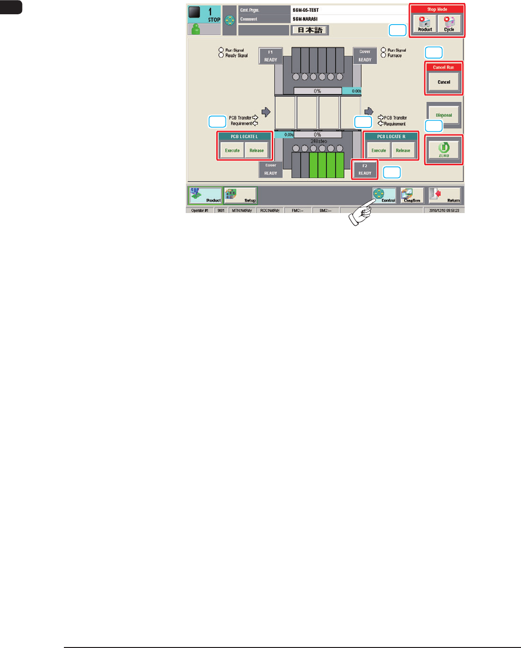
2.1 Control Menu
When the [Control] button is pressed on the common menu bar, the "Control
menu" window appears.
In the "Control menu" window, groups of the basic operation buttons are arranged.
[1]
[1]
[3]
[4]
[5]
[2]
F1B7
[1] PCB LOCATE
L,R
[Execute] Button
When the [Execute] button is pressed and within 10 seconds, the [START]
button on the operation panel is pressed, the backup base and clamp are lifted
and the PCB on the PCB positioning unit is positioned.
[Release] Button
When the [Release] button is pressed and within 10 seconds, the [START]
button on the operation panel is pressed, the backup base and clamp are
lowered and the positioned PCB is released.

1OM-1603
2-9
2. Operation Screen : Chap.2
1012-002
[2] [F1 READY] Button
[F2 READY] Button
When the [F1 READY] button [F2 READY] button is pressed, the feeder
ready switches on the main machine are turned ON/OFF, and feeder clamp
holding bar is locked/unlocked.
Note
The moving up/down operation of the feeder base is unavailable. If
needed, perform it using the feeder ready switches on the main machine.
Reference
Refer to "2.3 Feeder Ready Switches and Cover Lock Switches" in Chapter
1, for the feeder ready switches on the main machine.
[3] Stop Mode
[Product] Button
When this button is pressed, after the production of the PCB which is in
the course of the production, is completed, the PCB is discharged and the
automatic operation is stopped.
[Cycle] Button
When this button is pressed, after the component placement operation on the
PCB which is in the course of the production, is completed, the automatic
operation is stopped.
[4]
Cancel Run
[Cancel] Button
When the machine status is turned to "Pause", the [Cancel] button is
displayed. When the [Cancel] button is pressed, the "Pause" status is
cancelled and the machine is in the "Stop" mode.
[5] [ZERO] Button
After the [ZERO] button is pressed and within 10 seconds, the [START]
button on the operation panel is pressed, all the axes are zeroed.
[6] Language Change Buttons
Using these buttons, the language is changed to the one indicated on the
button.