1OM-1625-004_w.pdf - 第189页
1OM-1603 4-12 1. Specications : Chap.4 1012-005 Item Description Visual Field Approx. 12 × 12 mm Window Size Max. 9.0 × 9.0 mm Recognition (Process) Time Approx. 0.06 seconds / mark (including the time to capture an ima…
1OM-1603
4-11
1. Specications : Chap.4
1012-005
Item
Description
16. Memory Capacity
of Pattern
Program Data
Maximum Number of Steps : 20,000 steps/model (For repetitive patterns)
Maximum Memorized Number of Models : 24 models
Note : The above numbers are limited according to the capacity of the
pattern program data per model.
17. Input System and
Output System of
Pattern Program
Data
• Operated using the touch screen on the main machine and edited using the
keyboard/pointing device (Option).
• Pattern program data can be edited with the network terminal (Option).
• Data can be entered through the local area network (Ethernet) running from
the data storage device of the network terminal (Option).
• Data Transfer to Storage of Network Terminal (Option).
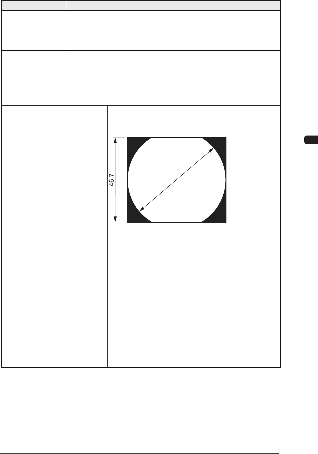
Visual Field φ 62 mm
The dimension in Y direction must be 46.7 mm.
Unit : mm
F1E10
18. Component
Recognition
Y (direction)
ø 62
Photo Image Front Lighting System
(Direct Recognition of Component by Front Lighting)
Note : Some limitation is imposed, depending on the types
of components.
Back Lighting System
(Recognition by Component Silhouette)
Note : Some limitation is imposed, depending on the types
of components.
In the back lighting system, specified nozzle are
required for the middle-size odd shaped nozzle and
the multi-functional nozzle on the multi-functional
head.
For the Back Lighting System, the static image is
shot using the camera.
T1E1-11
1OM-1603
4-12
1. Specications : Chap.4
1012-005
Item
Description
Visual Field Approx. 12 × 12 mm
Window
Size
Max. 9.0 × 9.0 mm
Recognition
(Process)
Time
Approx. 0.06 seconds / mark
(including the time to capture an image)
19. PEC Recognition
Photo Image Front Lighting System
(Recognition of Fiducial Mark by Front Lighting)
("Normal" or "Reverse" can be selected for each mark.)
20. Fiducial Marks Refer to "Fiducial Marks" for details.
Supply
Pressure
0.45 to 0.69 MPa (4.6 to 7 kgf/cm
2
)
Set Pressure 0.45 MPa (4.6 kgf/cm
2
)
Note : Min. 0.4 MPa (4.1 kgf/cm
2
) of air is necessary for
operation.
21. Air Supply
• Use the dry and clean air as follows
Moisture : Dew Point − 17 ℃ or lower (Atmospheric Pressure)
Oil : 0.1 mg/m
3
or less (ANR)
Dust : Solid Material 0.01 µm or less
22. Air Consumption Approx. 30 L/min (during automatic operation)
Approx. 110 L/min (when one feeder base moves up and down)
Approx. 220 L/min (when two feeder bases move up and down at the same
time)
23. Vacuum Pressure −93 kPa (70 cmHg)
24. Environmental
Condition
Temperature: 20
±
10
°
C
Humidity : 30 to 80 % (Avoid dew condensation)
Note : When the ambient temperature rises more than the surface of the
machine, dew condensation might occur under the condition described
below.
Note that dew condensation may cause the machine to break down.
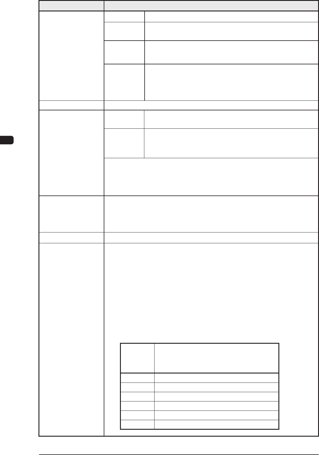
Condition of Dew Condensation
Dew condensation might occur when the difference (based on
"Humidity (%)") between the ambient and surface temperatures of the
machine reach the values or more in the table below.
Humidity
(%)
Differences between Ambient and Surface
Temperatures of Machine (Ambient
Temperature > Surface Temperature)
80 3 °C or more
70 6 °C or more
60 8 °C or more
50 10 °C or more
40 14 °C or more
30 18 °C or more
Altitude : 1,000 m or less above the sea level
T1E1-12

1OM-1603
4-13
1. Specications : Chap.4
Item
Description
25. Power Supply
200 ±
20 V AC, 3-Phase, 50/60Hz
Connected to the power supply unit (3-phase 3-wire system)
(The grounding cable should be connected to the PE terminal).
26. Maximum 7.4 kVA
Apparent Power
27. Power
Consumption/
Hour
Approx. 1.80 kWh
28. Dimensions
Approx. 1,280 (Width) mm (Including Input/Output Conveyor)
× 2,200 (Depth) mm
(Including Bank Feeder Change Cart)
× 1,450 (Height) mm
(1,910 mm : Including Tower)
29. Mass
Approx. 1,800 kg
(excluding. the Bank Feeder Change Carts and the tape feeders)
30. Environmental
Requirements for
Bank Feeder
Change Cart
Floor Gradient : 10/1000 or less
Note : The floor should be hard enough for the casters of the cart to move
smoothly.
32. Others
Standard Functions
• Component Library Teaching Function (GS-TR100)
• Placement Position Teaching Function (GS-TZ100)
• Application for BGA/CSP (GS-TB100)
• Automatic Recovery Function for Component Pickup Errors
• Component Pick-Up Position Teaching Function
• Delayed Recovery Function (Recovery Mode)
• Alternate Component Supply Function
• Pick-Up and Placement Up/Down-Axis (L-Axis) Control Function
• Pick-UP Position (X/Y) Correction Control Function
• Pocket outline recognition
• Two-stage placement Z-Axis speed reduction
• Nozzle existence check before pick-up
31. Input and Output
Conforming to the specifications of the SMEMA communications.
Interfaces
T1E1-13
1012-005