1OM-1625-004_w.pdf - 第194页
1OM-1603 4-17 3. Conditions for Component Placement : Chap.4 3. Conditions for Component Placement (1) When components are to be placed close to the previously-placed components or the obstacles, the shape of the vacuum …
1OM-1603
4-16
2. High-Speed Head Pick-up Component Size : Chap.4
1012-001
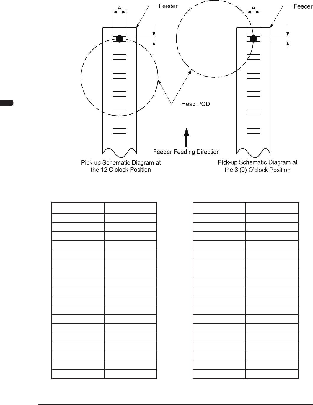
2. High-Speed Head Pick-up Component Size
(In the case that 15 components are to be picked up
at the same time).
B
B
F1E10-1
Component Size in the Pick-up
Operation at the 12 O’clock Position
Component Size in the Pick-up
Operation at the 3 (9) O’clock Position
Size A Size B Size A Size B
5.4 0.5 10.0 2.2
5.2 1.3 9.4 2.4
5.0 1.9 8.8 2.6
4.8 2.4 8.2 2.8
4.6 3.0 7.6 3.0
4.5 3.3 7.1 3.2
4.4 3.6 6.5 3.4
4.2 4.2 5.9 3.6
4.0 4.7 5.3 3.8
3.8 5.3 4.7 4.0
3.6 5.9 4.2 4.2
3.4 6.5 3.6 4.4
3.2 7.1 3.3 4.5
3.0 7.6 3.0 4.6
2.8 8.2 2.4 4.8
2.6 8.8 1.9 5.0
2.4 9.4 1.3 5.2
2.2 10.0 0.5 5.4
Note: Only the components that can be handled using the hi gh -sp e e d
nozzle with the diameter of 6mm or less, are used.
T1E4-1 T1E4-2
1OM-1603
4-17
3. Conditions for Component Placement : Chap.4
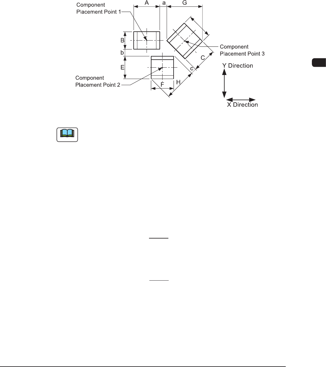
3. Conditions for Component Placement
(1)
When components are to
be placed close to the previously-placed
components or the obstacles, the shape of the vacuum nozzle becomes part
of the constraint condition. Refer to "List of Nozzle Types" for the shapes of
vacuum nozzles.
(2)
Adjoining
Distances between Components
(when
the component placement
position is taken into consideration)
F1E11
Note
(a) F1E11 shows that the vacuum nozzles are not protruding from the
outer shapes of components.
When components are placed, any placement deviation may be
caused by solder paste, glue, etc. Here, we don’t take account of
such deviation.
(b) AtoHintheabovegureshowthemaximumdimensionsincluding
the variations in the dimensions of each component. The minimum
adjoining distances (a, b, and c) of each component should be 0.2
mm.
(c) The minimum adjoining placement
position data for component
placement points 1 and 3 is
X Direction Data = + Min. 0.2 mm
(The Y direction data is not related.)
(d) The minimum adjoining placement position data for component
placement points 1 and 2 is
Y Direction Data =
+ Min. 0.2 mm
(The
X direction data is not related.)
(e) See F1E11 and obtain the minimum adjoining placement position
data for component placement points 2 and 3.
A + G
2
B + E
2
1012-005
1OM-1603
4-18
3. Conditions for Component Placement : Chap.4
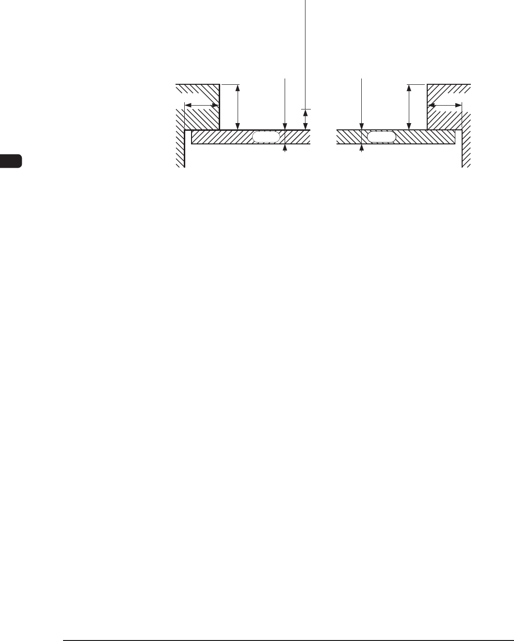
(3) Limit of Closest Distance to Obstacle
•
The closest distance between
an obstacle (See each sectional view.) and
the vacuum nozzle or component should be 0.5 mm or more.
The
upper
surface
of
the PCB is the reference plane.
0.5 ot 3.0
0.5 ot 3.0
3.0
0.2
3.0
0.2
erom ro mm 5.0
PCB PCB
(Rear Side Machine)(Front Side Machine)
ecnatsiD tsesolC fo timiL
Unit : mm
F1E12
1007-004