1OM-1625-004_w.pdf - 第56页
1OM-1603 1-1 1. What is the modular mounter? : Chap.1 1003-003 1. What is the modular mounter? This machine is provided with a batch recognition system by which various kinds of electronic components (simply called "…

1OM-1603
0908-002 1-B
1OM-1603
1-1
1. What is the modular mounter? : Chap.1
1003-003
1. What is the modular mounter?
This machine is provided with a batch recognition system by which various
kinds of electronic components (simply called "Components" hereinafter) can be
recognized in batch (non-stop y batch recognition) and realizes highly accurate
component placement on the PCBs at high speed. The machine is also equipped
with two beams, two heads, and two component recognition cameras, making
it possible to handle many different kinds of components in small lots or few
different kinds of component in large lots for diversied scales of production.
This machine introduces our latest technologies such as direct drive heads, X/
Y-axis linear motor driving, etc., (the performance proven by our direct drive
turret mounters) that have been used in the past actual production and is provided
with various functions for reduction of OOS (out of service) time. That is the
reason why this mounter is called "Modular Mounter with High Total Productivity
for Next Generation".
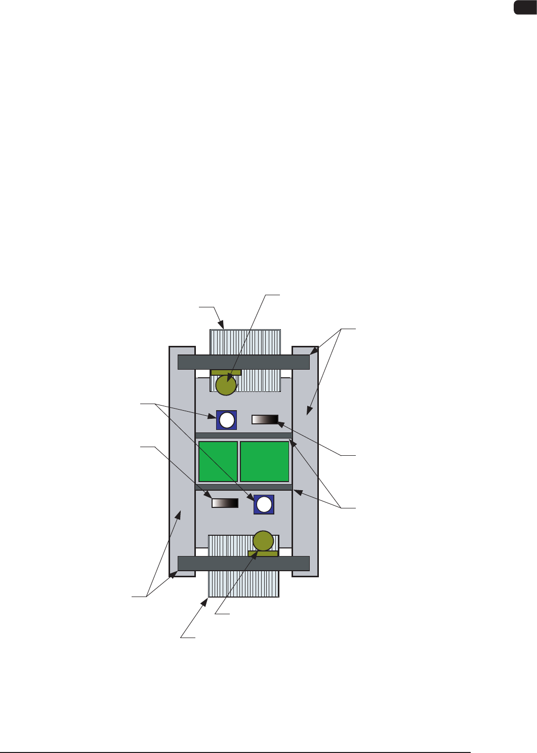
1.1 Location of Each Unit
Cart Installation Section
Cart Installation Section
XY Beam Section
Nozzle Stocker Section
Component Recognition Unit
Nozzle Stocker Section
PCB Transfer Section
Placement Head Section,
PEC Recognition Section
Placement Head Section,
PEC Recognition Section
XY Beam Section
F1A1

1OM-1603
1-2
1. What is the modular mounter? : Chap.1
1012-004
1.2 Main Features
Beam Section
•
XY-Axis Linear Motor Driving
The X/Y axis driven by linear motors and scales realized highly accurate
component placement at high speed, reducing vibration and noise.
The Y-axis twin driving made it possible to achieve highly accurate
positioning at high speed.
•
2-Beam and 2-Head Structure
The machine has two structure and each structure is provided with the front
and rear beams (2 heads and 2 beams in total).
The front and rear beams perform alternatively and repeatedly the component
placement and pickup operations, for efcient and continuous component
placement.
•
Head Mutual Delivery Function
Using the head mutual delivery function, the components on the feeder on
the other side of the machine can be picked up.
Also, the heads each in the front and rear sides can commonly use the option.
Head Section
•
Multi-Heads
Each head is provided with line sensors which can measure component
height. The results of the measurement are fed back, realizing the best
amount of pushing distances for high quality component mounting.
Each head holds fteen nozzles that pickup components in succession,
reducing the shuttling frequency of the beams for realization of high
throughput.
A simulation is made to determine the number of components to be placed
at a time, enabling the best selection in the number of nozzles for the
multiheads.
•
Component Thickness Measurement
The picked component thickness is measured using a line sensor and the
acquired data is fed back to the height for component placement.
The vacuum nozzle detection function enables detection of an overcarried
component, realizes highly accurate detection, and ensures high quality
placement.