1OM-1625-004_w.pdf - 第63页
1OM-1603 1-8 2. Name and Function of Each Section : Chap.1 2.2.2.1 Feeder Ready Switches The feeder ready switches are used to indicate that the feeder bases are set ready and each switch is employed in each feeder block…
1OM-1603
1-7
2. Name and Function of Each Section : Chap.1
1012-005
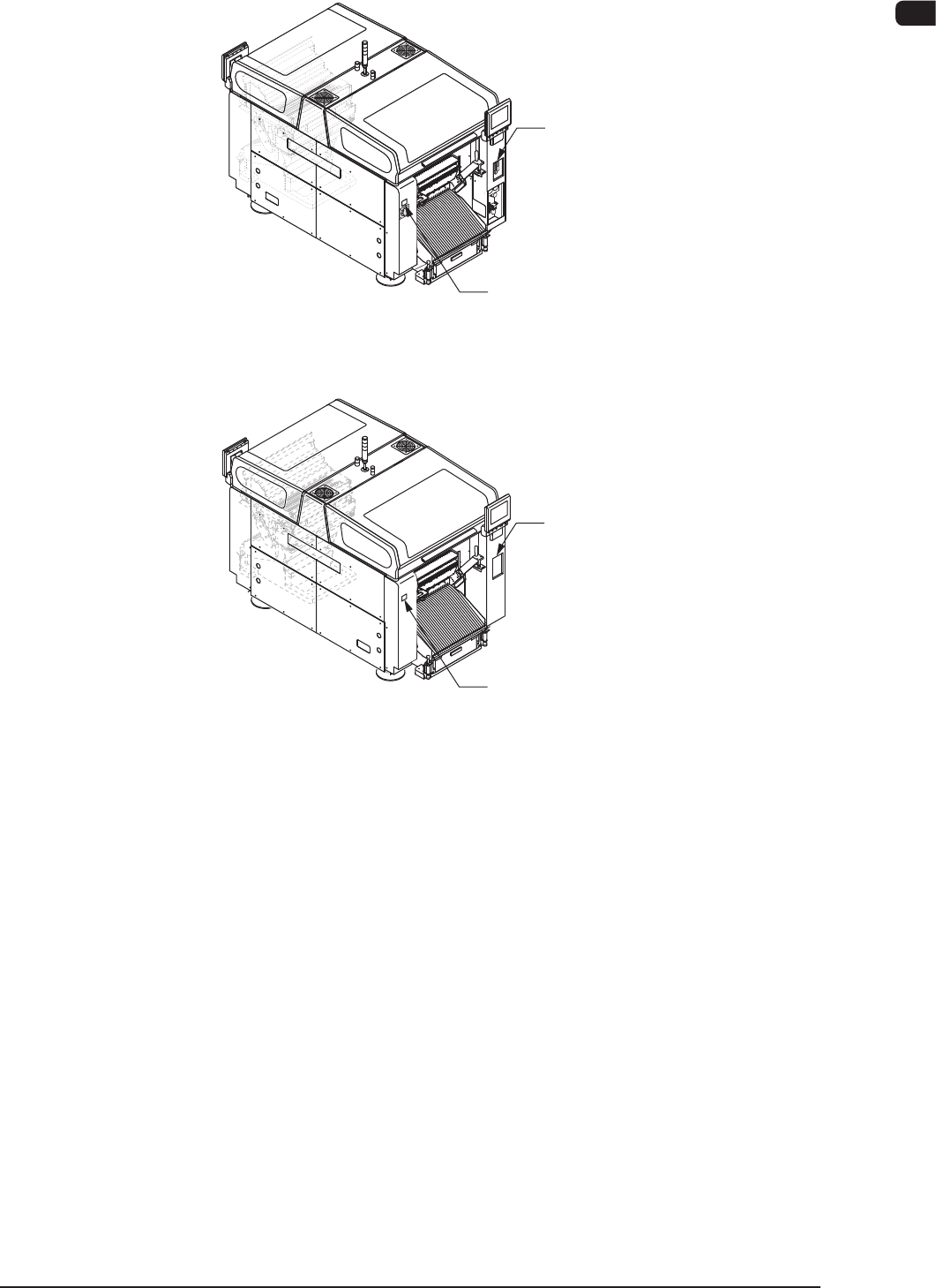
2.2.2 Feeder Ready Swtches and Cover Lock Switches
Cover Lock Switch
([Cover READY] Button)
Feeder Ready Switch
([F2 READY] Button)
Front Side of Machine
Rear Side of Machine
Cover Lock Switch
([Cover READY] Button)
Feeder Ready Switch
([F1 READY] Button)
F1A5
1OM-1603
1-8
2. Name and Function of Each Section : Chap.1
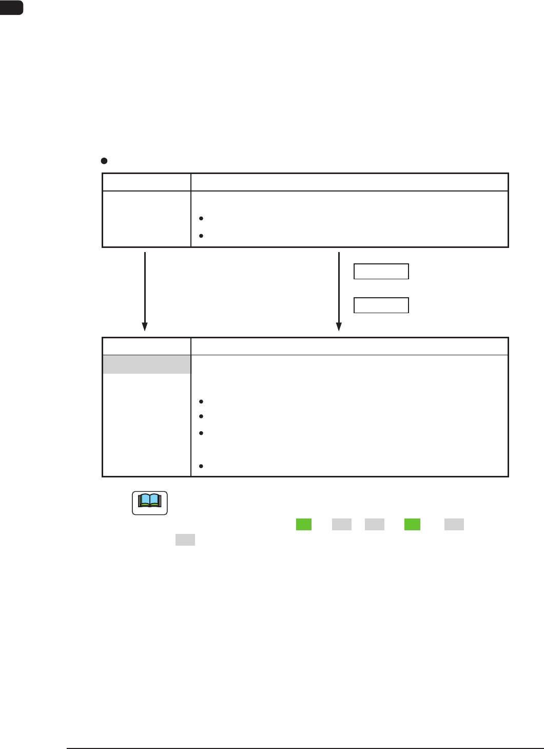
2.2.2.1 Feeder Ready Switches
The feeder ready switches are used to indicate that the feeder bases are set ready
and each switch is employed in each feeder block.
When the [START] button is pressed, the feeder clamp is activated and when the
machine is stopped or paused, the feeder clamp is released.
Also, this function enables the operator to perform operations while checking the
feeder pickup sections.
Switch ON (Short Push)
LED OFF
S witch Operations and Tr ansition of Machine Condition
[Ordinary Operations with Machine in "STOP" (or "PAUSE") Mode]
Feeder Ready Switches
Switch Status Machine Status
Power Supply ( 24 V) to Feeders :
Switch Status Machine Status
LED OFF
"Replacement and Setup Operations of Feeder Bank
Carriage Cart" Possible
Power Supply ( 24
V) to Feeders :
Intercepted
Feeder
Attachment/Detachment Operation :
Possible
Power Supply to Connector for
feeder Base Installed on Main Machine
:
Intercepted
Note
During the transition of the machine status along with the above-described
switch operations, the FEEDER READY switches flicker , regardless of a
LED lighting pattern such as "ON" to "OFF", "OFF" to "ON", or "OFF" to
"OFF".
Switch ON (Short Push)
Powered
:
UnlockedFeeder Base Drop Prevention
Feeder
Attachment/Detachment Operation :
Possible
LED OFF
"Operation of Feeder Ready" Permitted by Operator
1012-005
1OM-1603
1-9
2. Name and Function of Each Section : Chap.1
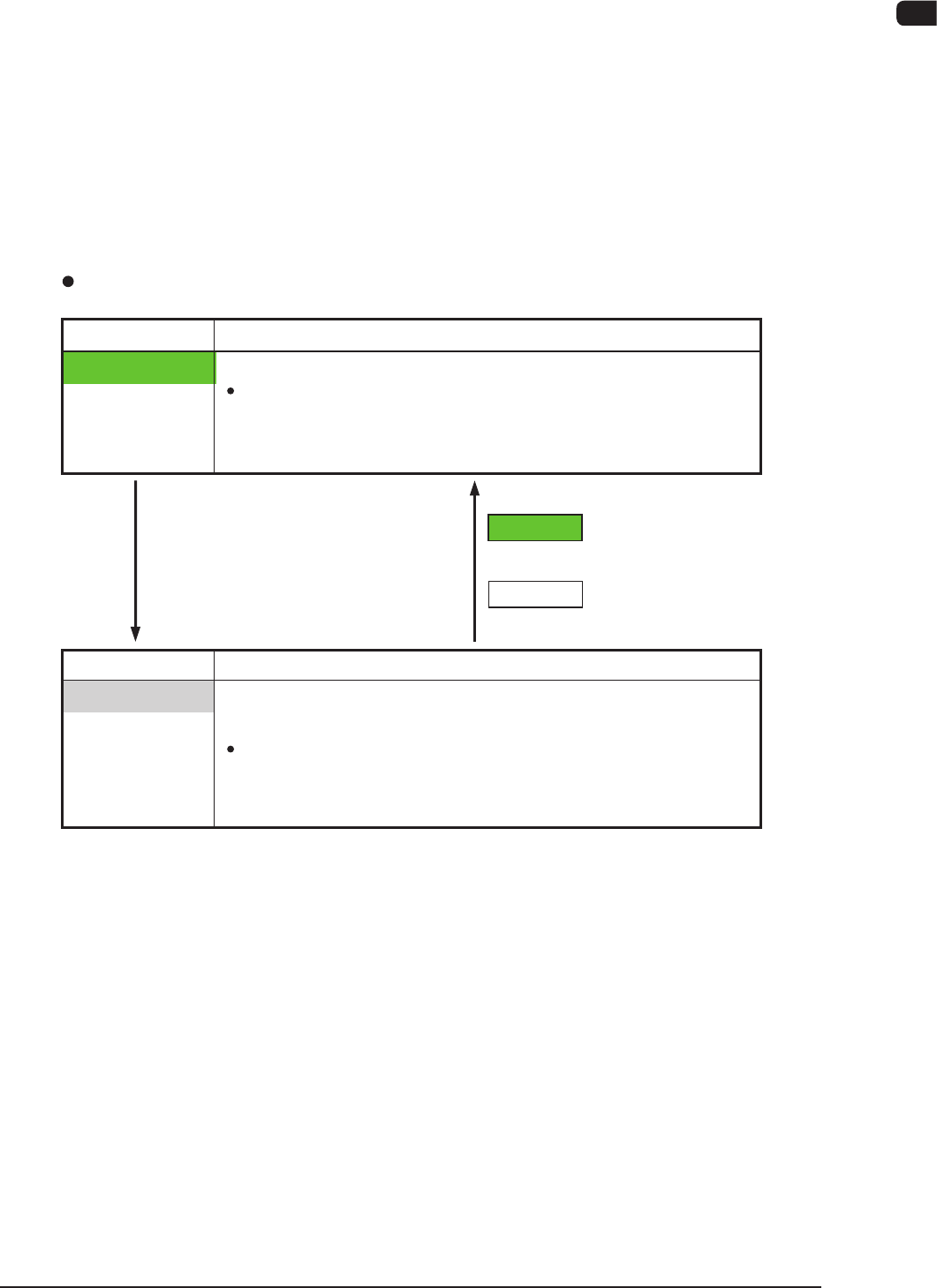
2.2.2.2 Cover Lock Switches
The Cover Lock Switches are used to permit the automatic operation of the
selected stage section. Each stage is provided with a Cover Lock Switches.
While the LED of the switch is ON, the transparent cover (door type) on the
selected stage cannot be opened because it is locked electromagnetically.
The LED cannot be turned on with the transparent cover kept open.
In addition, no power is supplied to the main circuit of the beam when the LED of
the "Cover Lock Switches" are turned ON.
The main circuit is powered only when the LEDs of both related stage and
"Feeder Ready Switches" are turned ON.
Switch ON
LED ON
Switch ON
LED OFF
Cover Lock Switches
Switch Status Machine Status
LED ON
"Cover Locking Operation" Permitted by Operator
Electromagnetic Locks of
Transparent Covers
(Door Type)
:
Locked
(Cover Opening Impossible)
Switch Status Machine Status
LED OFF
"Cover Locking Operation" Rejected by Operator
Interception of Main Circuit for Pertinent Beam
Electromagnetic Locks of
Transparent Covers :
Unlocked
(Cover Opening / Closing Possible)
1012-005