1OM-1625-004_w.pdf - 第70页
1OM-1603 1-15 2. Name and Function of Each Section : Chap.1 1012-004 2.3.3 Auxiliary Lamps The auxiliary lamps are used to indicate in which block the machine status (indicated by the tower lamp) is generated. Auxiliary …
1OM-1603
1-14
2. Name and Function of Each Section : Chap.1
1012-003
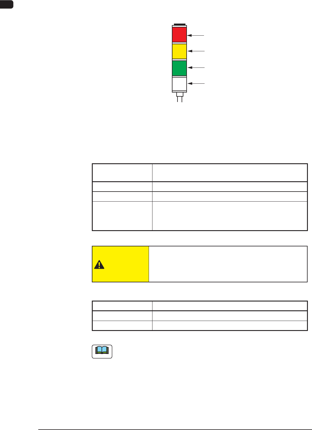
2.3.2 Light Tower
The light tower indicates the condition of the machine with the lamps and buzzer
sounds.
Red
Yellow
Green
Buzzer
Light Tower
Light Tower F1A11
•
Lamp Colors (ON Mode)
The machine is factory-adjusted upon shipment.
Lamp Colors
(ON Mode)
Machine Condition
Red
Error (Operation Stopped)
Yellow
Component Shortage (Warning)
Green
Automatic Operation
When the machine is in the standby mode, this lamp
ickers.
T1A3
CAUTION
When the green lamp of the light tower is ON or ickering
(ON and OFF), it indicates that the static machine is in the
"Automatic" mode (standby mode).
•
Buzzer
Buzzer Machine Condition
Continuous Sound
Emergency Stop
Intermittent Sound
Error
T1A4
Note
The condition of the machine corresponding to the parameters specied for each
lamp color and buzzer sound can be changed in the "Machine Setup" window.
1OM-1603
1-15
2. Name and Function of Each Section : Chap.1
1012-004
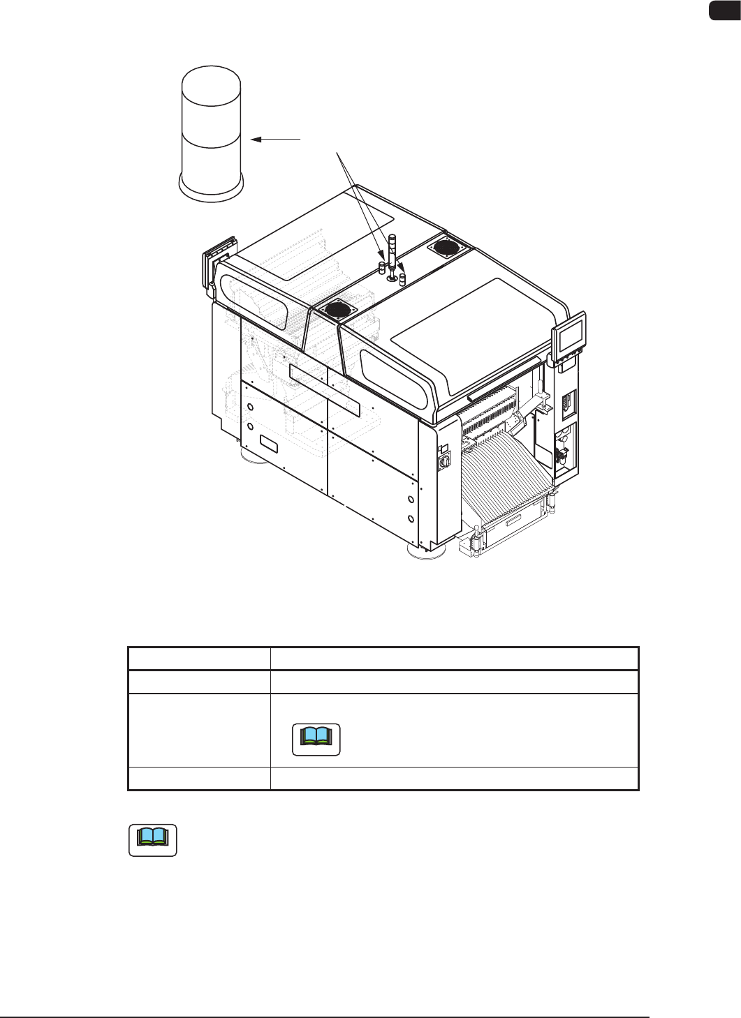
2.3.3 Auxiliary Lamps
The auxiliary lamps are used to indicate in which block the machine status
(indicated by the tower lamp) is generated.
Auxiliary Lamps
F1A12
•
Lighting Condition of Lamps
Lighting Condition Machine Status (based on each block)
ON Normally Running or Under Operation
ON and OFF
(Flickering)
Error or Component Shortage
Note
When an error is not related to any block, all
auxiliary lamps icker.
OFF Stop Mode
T1A5
Note
When component shortage has occurred, replenish the component supply.
1OM-1603
1-16
2. Name and Function of Each Section : Chap.1
1012-005
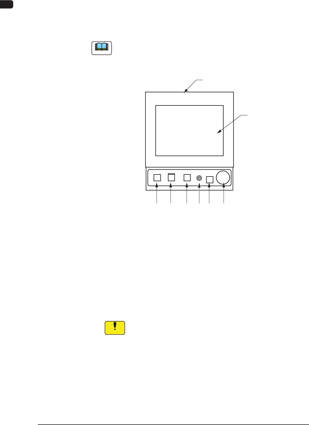
2.3.4 Operation Section
The machine is equipped with the touch screens and operation panels for machine
operations on both front and rear sides.
The [PNL CHANGE] buttons on the operation panels can be used to select and
activate either the front or the rear operation panel.
Note
The keyboard and mouse are not attached, but they can be attached as options.
The following operation buttons and switch are arranged on the operation panel.
[2] [3] [4] [7]
[1]
Operation Panel
[5]
[6]
F1A13
[1] Touch Screens
The windows for operations are displayed on the front rear touch screens.
Various operations can be performed by nger-touching the buttons that
appear on the screen.
Notes on Handling Touch Screen
•
Since the touch screen uses the molecules in liquid crystals, handle it like
glass. Do not apply any strong pressure or shock to the surface.
Notice
Do not apply any strong pressure or shock to the touch screens.
Otherwise, they will be damaged.
Do not press the touch screens with a force of 0.79N (80 g) or
more.