1OM-1625-004_w.pdf - 第75页
1OM-1603 1-20 3. Mechanism for Surface Mounting : Chap.1 1012-004 3. Mechanism for Surface Mounting 3.1 Location of Related Units Component Recognition Section Component Recognition Section XY Beam Section Placement Head…

1OM-1603
1-19
2. Name and Function of Each Section : Chap.1
1007-004
[6] [PNL CHANGE] Button
This button is used to select either the front or the rear operation panel. This
button is prepared on each operation panel. When the LED of the button is
ON, it indicates that the corresponding operation panel is available.
When this button is pressed with the LED "ON", the operation panel is set in
the "LOCK" mode and the "LOCK" lamp illuminates.
When the operation panel is set in the "LOCK" mode, the other operation
panel on the opposite side cannot be selected on the other operation panel
side.
To cancel the "LOCK" mode, press this button again.
Note
(a) While the LED of this button is ON, the followings become
available.
•
Touch Screen
•
[START] and [STOP] Buttons and [EMERGENCY STOP] Switches
(b) The [STOP] buttons and the [EMERGENCY STOP] switches are
always available, regardless of which [PNL CHANGE] button is
selected.
(c) When both operation panels are not set in the "LOCK" mode and the
[PNL CHANGE] button on the unavailable operation panel side is
pressed, the unavailable operation panel is selected and set available.
(d) When the operation panel is not locked and the [STOP] button on
the unselected operation panel is pressed, the operation panel on the
pressed button side becomes activated automatically
.
[7] [EMERGENCY STOP] Switch
Press this switch to immediately stop the machine in an emergency.
When this switch is pressed, the machine stops running immediately and the
[POWER ON] button on the operation panel illuminates in red.
1OM-1603
1-20
3. Mechanism for Surface Mounting : Chap.1
1012-004
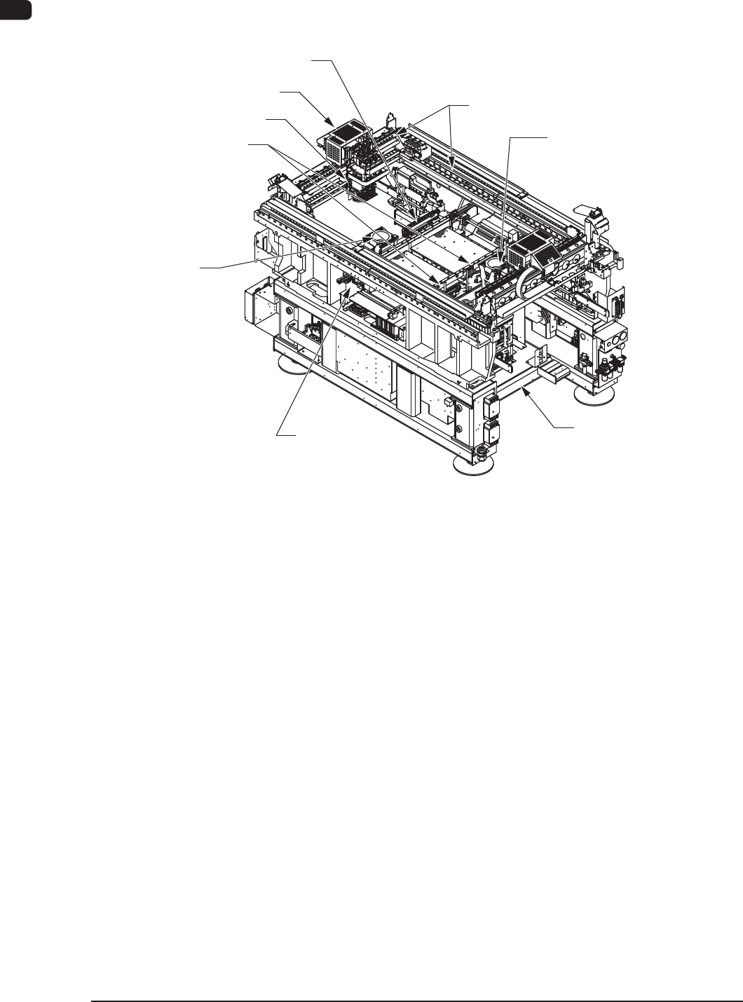
3. Mechanism for Surface Mounting
3.1 Location of Related Units
Component Recognition
Section
Component
Recognition Section
XY Beam Section
Placement Head Section
PCB Positioning Section
Cart Installation Section
PCB Transfer
Section
Nozzle Stocker Section
PEC Recognition Section
F1A16
1OM-1603
1-21
3. Mechanism for Surface Mounting : Chap.1
1012-004
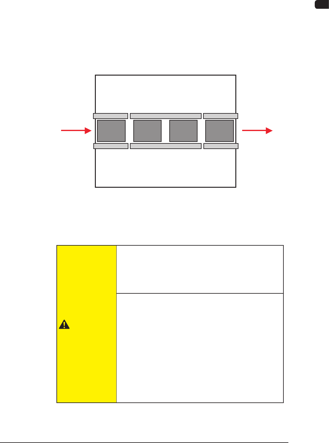
3.2 PCB Transfer Section (PCB Input and Output Sections)
The PCB transfer mechanism works to transfer the PCB (sent from the input
machine) to the area just before the PCB positioning section and carries out the
component-placed PCB to the output machine.
The PCB sent from the input machine is transferred to the area just before the
PCB positioning section by the PCB input section.
The component placed PCB transferred from the PCB positioning section on the
output side is carried further to the output machine by the PCB output section.
Input
Machine
Output
Machine
PCB Input
Section
Positioning
"L"
Section
Positioning
"R"
Section
PCB Output
Section
F1A17
The PCB input section and PCB output section also serve as buffers.
Also, these sections are used as connecting sections to the external machines or to
the PCB positioning section.
CAUTION
Before operating the machine, conrm that there are no
people around the machine (especially, the other side of
the machine operation) and no objects such as tools and
parts are left around the machine.
When a PCB is trapped in the PCB receiving area
between the main machine and the input or the
output machine, be sure to stop the machine before
removing the PCB.
Depending on the setting of the PCB discharge from the
input machine to the output machine, the conveyor might
be moved in direction Y because the "PCB Direction Y
Arrangement Operation" is performed at the moment
when the PCB is removed. In such case, your nger might
be caught.