1OM-1625-004_w.pdf - 第82页
1OM-1603 1-27 3. Mechanism for Surface Mounting : Chap.1 1012-004 3.7 Nozzle Stocker (Housing) Section This section is equipped with a mechanism by which the vacuum nozzles can be stored. A placement head moves to the ar…
1OM-1603
1-26
3. Mechanism for Surface Mounting : Chap.1
0908-002
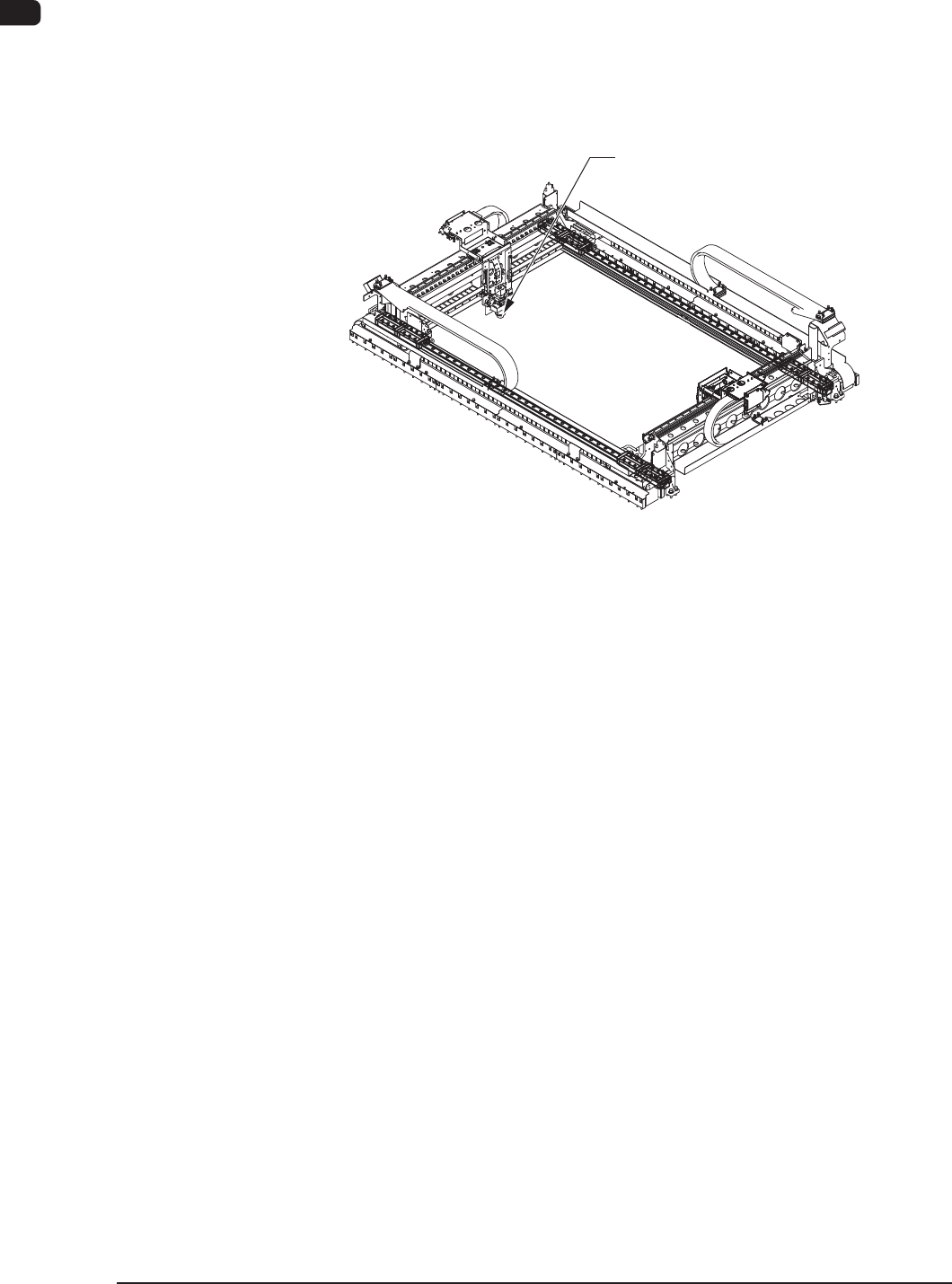
3.6 PEC Recognition Section
Each beam is equipped with a PEC recognition camera and a light source for
illumination, making a pair with the placement head.
The PEC recognition camera is used to detect the ducial marks on a PCB and
the amount of the positional deviation from the ducial mark coordinate data is
calculated to automatically correct the position of a component to be placed.
PEC Recognition Camera
F1A22
The main functions of the PEC recognition section are to detect the position
of a ducial mark and determine the shape of the component. In addition to
those functions, this section works to detect the position of a feeder and make a
positional correction of the captured y image.
1OM-1603
1-27
3. Mechanism for Surface Mounting : Chap.1
1012-004
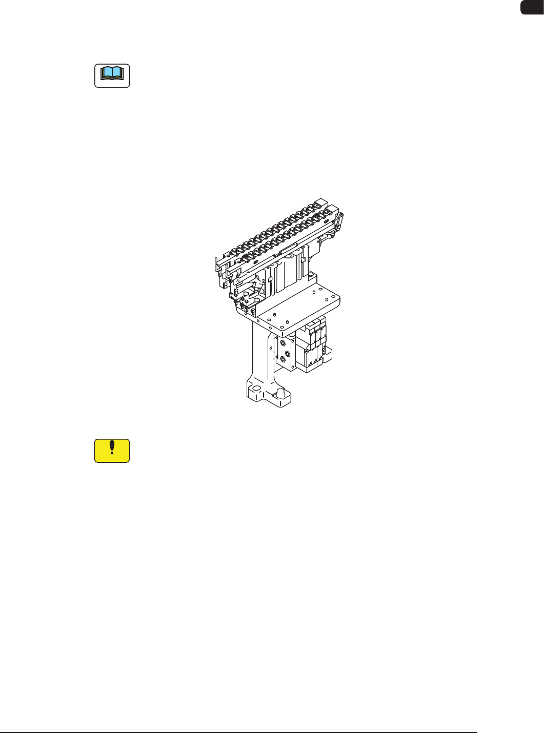
3.7 Nozzle Stocker (Housing) Section
This section is equipped with a mechanism by which the vacuum nozzles can be
stored.
A placement head moves to the area above the nozzle stocker according to the
pattern program and picks up a vacuum nozzle or puts it back in place.
Note
(a) There are three types; nozzle stocker for high-speed nozzle, nozzle stocker
for multi-functional nozzle, and the nozzle stocker for middle - size odd
shaped nozzle (option).
They are used depending on the vacuum nozzle type to be used.
(b) Each block can be provided with two nozzle stockers for the high-speed
nozzle, or only one nozzle stocker for the multi-functional nozzle (standard
specication). Two or more nozzle stockers can be installed on each block
(optional specications).
Hight-Speed Nozzle Stocker (Appearance) F1A23
Notice
(a) Do not put any foreign object in the nozzle stocker section.
Otherwise, the machine will break down.
(b) Do not bring any magnetized object such as a magnet close to the
vacuum nozzles.
Otherwise, an error may occur during component picks and
placement.
1OM-1603
1-28
3. Mechanism for Surface Mounting : Chap.1
1012-005
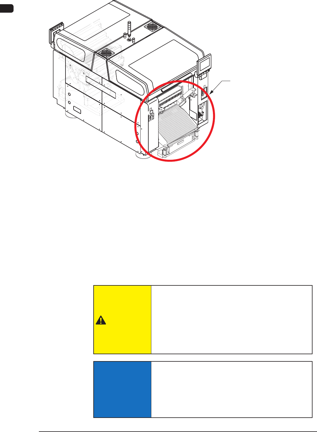
3.8 Cart Installation Section
Cart Installation Section
F1A22-1
The cart installation section is equipped with a mechanism by which the bank
feeder change cart is setup. The components are supplied from the tape feeder
attached onto the feeder base in the bank feeder change cart.
Each feeder base is provided with a "Fdr No." plate that indicates where to
allocate the feeders.
When a component shortage error is generated or a feeder has trouble and the
components cannot be picked up subsequently, the alternative feeder slot No. is
selected to continue the automatic operation. (Feeder Alternate Operation).
In this case, another slot No. across the front and rear beams can be selected.
CAUTION
When a tape feeder is attached or detached, be sure
not to drop it.
Otherwise, a foot injury will result or the feeder itself may
be damaged.
Carefully handle each feeder one by one and do not drop
any.
NOTICE
Attach the tape feeder correctly onto the feeder base
rail.
In the case that the tape feeder is attached incorrectly, it
might strike against the head section or a pick-up error
might be caused.