1OM-1625-004_w.pdf - 第85页
1OM-1603 1-30 3. Mechanism for Surface Mounting : Chap.1 1012-005 CAUTION Hazardoustoyourhandsandngers! • Be sure to hold the handle to move the bank feeder change cart. • Be careful not to hit your hand against …
1OM-1603
1-29
3. Mechanism for Surface Mounting : Chap.1
1003-003
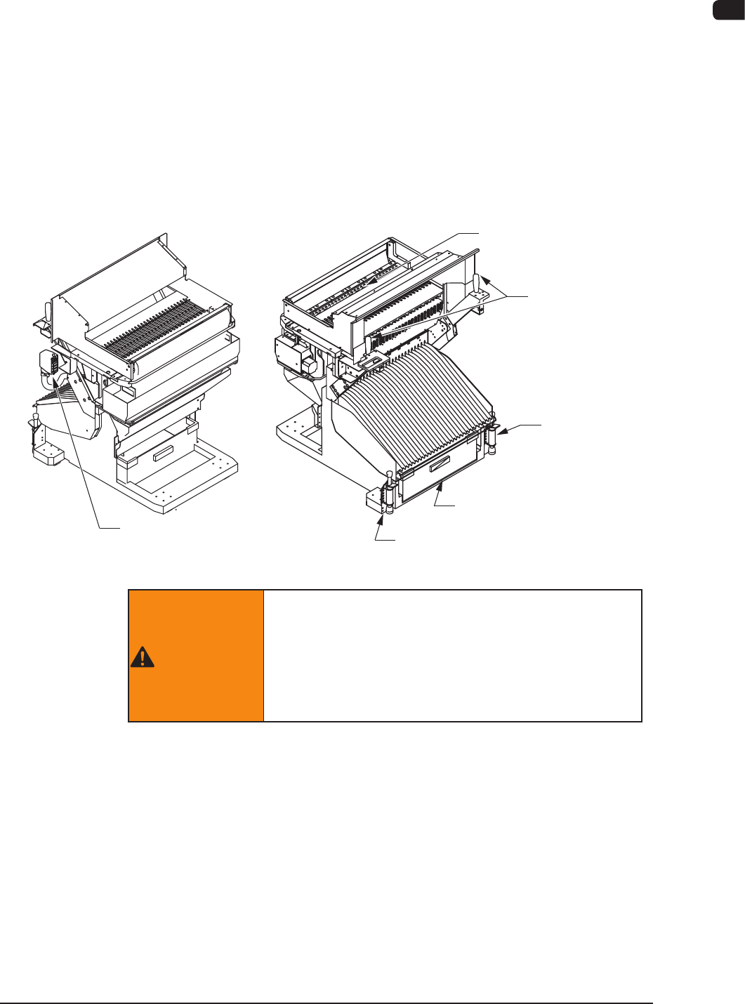
3.8.1 Bank Feeder Change Cart
The bank feeder change carts are used to install the feeder base to the main body
of the machine.
By using a bank feeder change cart, it becomes possible for the whole body of the
feeder base to be replaced with another one at a time.
When the feeders are prepared on the spare cart, a bank feeder change cart can
easily be replaced with the spare one, greatly shortening the time of a model
change operation (feeder replacement).
The bank feeder change cart is equipped with a scrap box that can be used to
collectively dispose the tape chips that were cut off when components were
supplied from the tape feeders.
Feeder Base
Handle
Stopper
Scrap Box
Stopper
Connector
F1A25
WARNING
If the bank feeder change cart is not set, a clearance
will be left at the feeder setting area and the operator
will be exposed to danger.
Be sure to use the machine with the bank feeder
change carts being attached.

1OM-1603
1-30
3. Mechanism for Surface Mounting : Chap.1
1012-005
CAUTION
Hazardoustoyourhandsandngers!
•
Be sure to hold the handle to move the bank feeder
change cart.
•
Be careful not to hit your hand against the cover while
installing the bank feeder change cart onto the main
machine.
Watch
yourstep!
•
Be careful not to hit your foot against the cart while
moving the bank feeder change cart.
Especially, the resistance against cart movement may
change rapidly when the oor is ragged and the cart
gets caught on the oor or a sheet is used and the cart
gets caught at the edge or a slackened portion of the
sheet.
•
Make sure to insert the feeder into the deep end.
When the tape feeder is mounted onto the feeder
carriage, make sure that it has been inserted into the
deep end and xed securely.
In the case that it has not been xed securely, the tape
feeder might fall, which might cause a lower leg injury
or damage to the feeder.
1OM-1603
1-31
3. Mechanism for Surface Mounting : Chap.1
1007-004
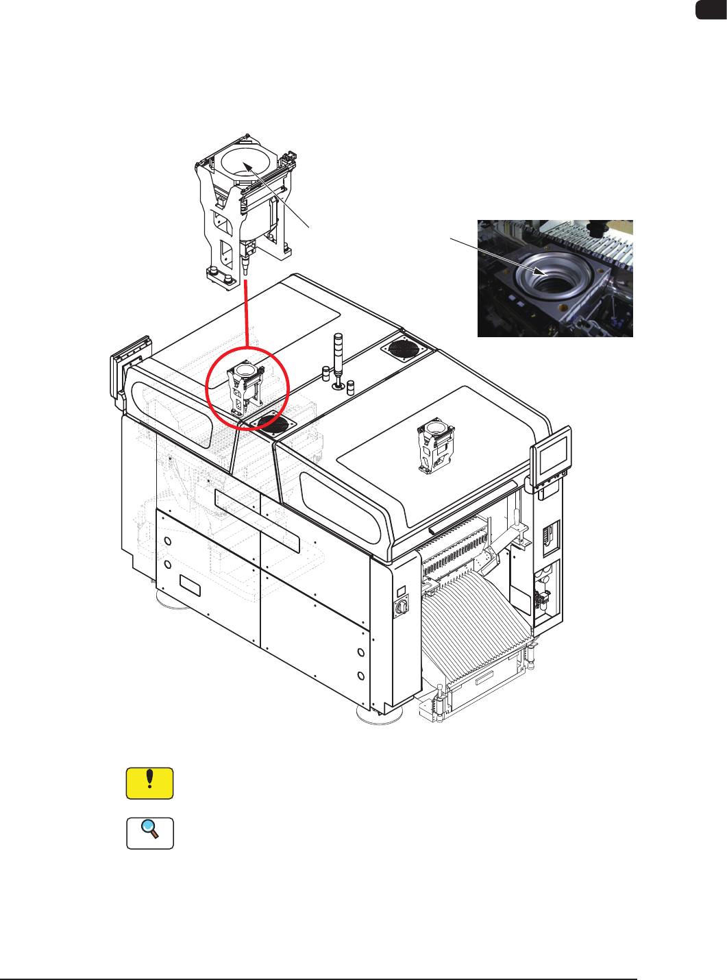
3.9 Component Recognition Section
Each beam has a component recognition camera and a light source for
illumination within its coverage area. The camera and the light source are used to
inspect (recognize) the component picked up by a vacuum nozzle.
The back and front lighting recognition systems are prepared for component
recognition. Either one of them is selected automatically according to the lighting
mode specied in the component library data.
Hood
(for BGA components)
F1A26
Notice
Do not stain the component recognition camera protective glass. Doing
so might lower the recognition accuracy.
Reference
When the protective glass becomes dirty, refer to "3.2.3 Recognition Camera
Unit" in Chapter 1, Volume 4.