1OM-1625-004_w.pdf - 第94页
1OM-1603 1-39 4. Surface Mounting Mechanism : Chap.1 1007-004 4.6 Component Recognition Each head is also provided with a line sensor. The line sensor is used to detect a component to be picked up and a vertical componen…
1OM-1603
1-38
4. Surface Mounting Mechanism : Chap.1
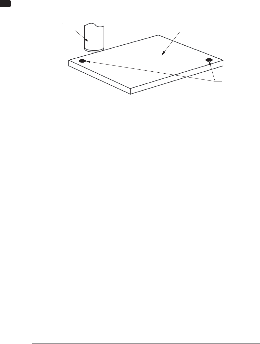
4.3 PEC Recognition
The PEC recognition camera detects the ducial marks on the PCB and the
positional deviations are calculated to correct the position of the components to be
placed.
PEC Recognition
Camera
Fiducial Marks
PCB
PEC Recognition
F1A33
4.4 Component Supply
The tape feeder on the feeder base is shifted to the position where the components
must be supplied.
The placement head is also shifted in the X and Y directions by the X/Y beam and
picks up a component. After that, it places the picked component on the PCB.
4.5 Component Picks
The vacuum nozzles on the placement head are used to pick up the components.
1012-002
1OM-1603
1-39
4. Surface Mounting Mechanism : Chap.1
1007-004
4.6 Component Recognition
Each head is also provided with a line sensor. The line sensor is used to detect a
component to be picked up and a vertical component. It is also used to measure
the component thickness.
The image of the component picked up by the vacuum nozzle is captured by the
component recognition camera for the inspection.
The back and front lighting recognition systems are adopted for component
recognition with the component recognition camera. Either one of the systems is
selected automatically according to the lighting mode specied in the component
library data.
Component Recognition Process
The following three operations are performed in the component recognition
system.
•
Component Detection
All components are regarded as object components for the detection.
•
Component Inspection
Various inspections are made according to the component library data.
•
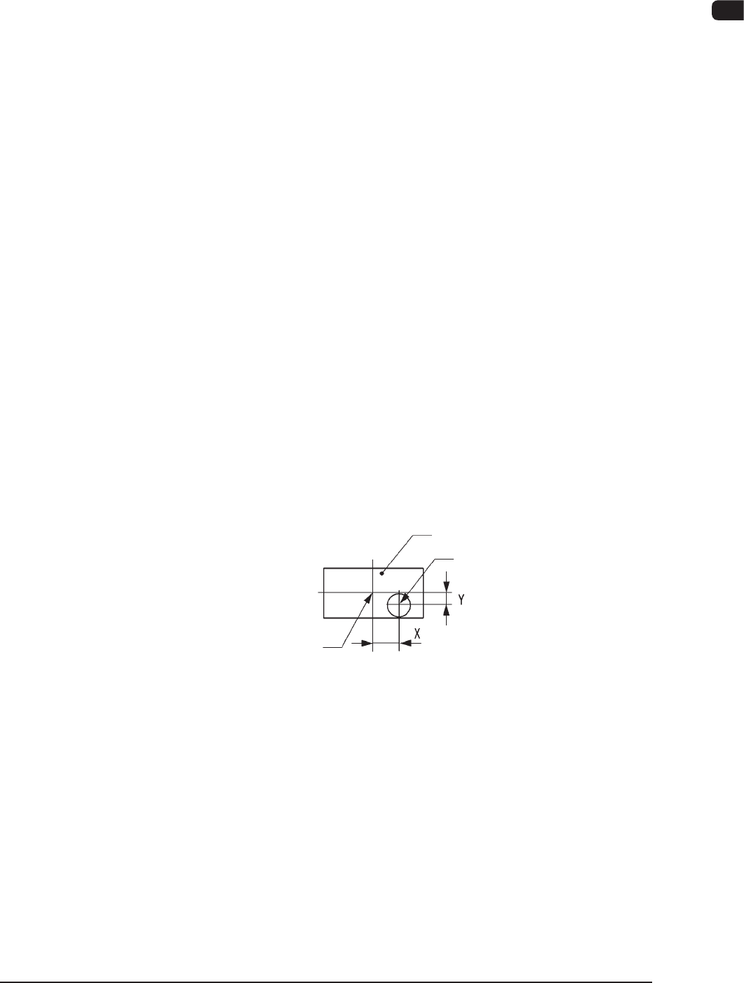
Measurement of Component's Positional and Angular Deviations
Measured are the positional deviations (X, Y) and the angular deviation (
q
)
between the centers of the component recognition camera and the center of
component.
Component
Center of Component
Vacuum Nozzle
State of Component Picked Up by Vacuum Nozzle F1A34
1OM-1603
1-40
4. Surface Mounting Mechanism : Chap.1
1012-004
Recognition Correction (Angular Correction)
The picked component is adjusted to the angle (placement direction) of placement
specied in the pattern program by rotating the head. At this time, the angular
deviation (
q
) detected through component recognition is also corrected.
Component
F1A35
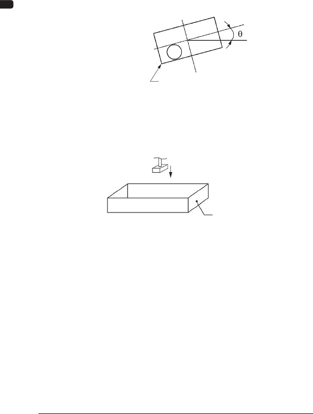
Component Discharge (Component Storage Box)
When a recognition error occurs during the component recognition, the placement
head moves to the component storage box and discharges the error-caused
component.
Component Storage Box
Component Discharge F1A36