6241f - 第15页
Page 7 GS-394-02 This is a typical CAD file which may be output from a wide variety of different CAD systems. This file includes SMC and IMC information, with component information stored for the IMC components. The comp…
Page 6 GS-394-02
BOM-CAD Link: A user-defined alphanumeric string
which links a line of data in the CAD file to a component ID
in the Bill of Material (BOM) file.
Ignore: If the CAD file contains data that does not fit any of
the fields, IM-UPS may be configured to ignore this data.
A sample CAD file format is given with a brief explanation.
This file format is provided for reference only and is an ex-
ample of a typical CAD output.
CAD Data Requirements
ASCII File Format — Incoming CAD files must conform to the
American National Standard Code for Information Interchange
(ASCII). In order to accommodate a wide variety of CAD file
formats, the APE uses either a generic columnar or separator
data translation technique. All data contained in the CAD file
is identified by a position in a definition created by the user.
CAD File Requirements
X Coordinate: The X centroid coordinate location on the
board.
Y Coordinate: The Y centroid coordinate location of the
component insertion.
Theta: The rotation of the component on the board.
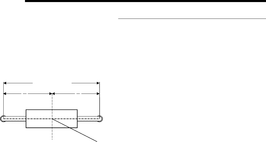
Insertion Lead Span: The distance between the centerlines
of the component leads.
Reference ID: The name assigned to the component makes
it unique to all other components in the product.
Component ID: The name of the component as it is found in
the component database.
Alias ID: The name of a component in the database to which
this component is aliased (optional).
Centroid (Top View)
Length = "L"
L
2
L
2
X, Y
Page 7GS-394-02
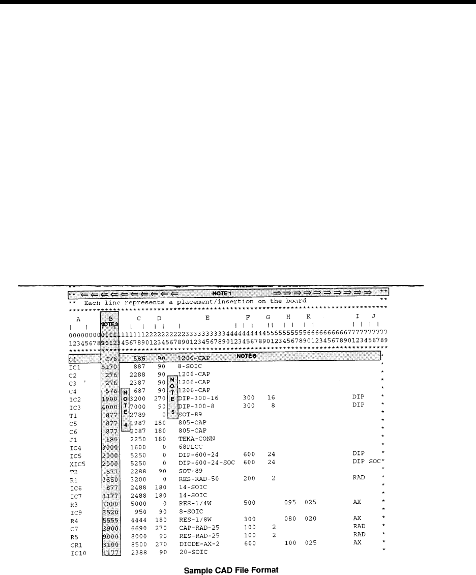
This is a typical CAD file which may be output from a wide variety of different CAD systems.
This file includes SMC and IMC information, with component information stored for the IMC components.
The component information for Surface Mount components will be obtained from the master .DEF files.
IMC component information will be obtained from this file and placed into the Component Library.
Information in the CAD file:
A = REFERENCE DESIGNATOR F = SPAN
B = X COMPONENT CENTROID COORDINATE G = NUMBER OF LEADS
C = Y COMPONENT CENTROID COORDINATE H = AXIAL BODY DIAMETER
D = ORIENTATION I = MACHINE TYPE
E = PART NUMBER/COMP ID J = DIP SOCKET
K = AXIAL LEAD DIAMETER

Page 8 GS-394-02
Sample CAD File Format Notes
1. Maximum file width can not exceed 256 columns.
2. Headerlines, often output by the CAD system, may be used.
The CAD Translator allows the user to define the quantity of
lines containing the file header. This information is for operator
use only and is not used by the CAD Translator.
3. Format Type: The format of file. This can be either Table or
Separator format (Table is the default).
Table format uses predefined columns for each data type. For example,
the reference ID column may be defined as 10 characters. The actual
reference ID in the CAD file can contain up to 10 characters. It does not
matter if there is data in every column.
Separator format uses a character (comma, space, dash, etc.) to
separate data fields. Each line of data must contain the same data
types in order for auto detect to work.
# of Fields: The number of fields in the file.
# of Lines: The total number of lines in the file.
4. The CAD file must be devoid of all special control characters
such as Tabs. (Note that special characters shown are for
illustration purposes only and cannot be contained in the
actual CAD file. These characters include boxes, arrows.)
5. CAD data is limited to one component per data file line or
row. Additional components are specified on additional lines
of the CAD file. There must be no blank lines or rows
between any rows of CAD data. Markers such as {EOF}
must not be present at the end of the CAD file.
Additional APE Features
• Import of Existing UICS Patterns — UICS patterns are con-
verted to IM-UPS products.
• Program Optimization — Optimization via “Nearest Neighbor”
insertion path.
• Component Identifier (part number) and Reference Designator
are now included in Product Information — the addition of
component identifier and reference designator in programs
supports improved status message reporting and management
data tracking by component identifier.