6241f - 第17页
Page 9 GS-394-02 Off-Line Pattern Programming Specifications The creation of a "product" (pattern program) can be completed on- line, utilizing the machine's embedded P.C., or off-line, using a suitable st…

Page 8 GS-394-02
Sample CAD File Format Notes
1. Maximum file width can not exceed 256 columns.
2. Headerlines, often output by the CAD system, may be used.
The CAD Translator allows the user to define the quantity of
lines containing the file header. This information is for operator
use only and is not used by the CAD Translator.
3. Format Type: The format of file. This can be either Table or
Separator format (Table is the default).
Table format uses predefined columns for each data type. For example,
the reference ID column may be defined as 10 characters. The actual
reference ID in the CAD file can contain up to 10 characters. It does not
matter if there is data in every column.
Separator format uses a character (comma, space, dash, etc.) to
separate data fields. Each line of data must contain the same data
types in order for auto detect to work.
# of Fields: The number of fields in the file.
# of Lines: The total number of lines in the file.
4. The CAD file must be devoid of all special control characters
such as Tabs. (Note that special characters shown are for
illustration purposes only and cannot be contained in the
actual CAD file. These characters include boxes, arrows.)
5. CAD data is limited to one component per data file line or
row. Additional components are specified on additional lines
of the CAD file. There must be no blank lines or rows
between any rows of CAD data. Markers such as {EOF}
must not be present at the end of the CAD file.
Additional APE Features
• Import of Existing UICS Patterns — UICS patterns are con-
verted to IM-UPS products.
• Program Optimization — Optimization via “Nearest Neighbor”
insertion path.
• Component Identifier (part number) and Reference Designator
are now included in Product Information — the addition of
component identifier and reference designator in programs
supports improved status message reporting and management
data tracking by component identifier.

Page 9GS-394-02
Off-Line Pattern Programming
Specifications
The creation of a "product" (pattern program) can be completed on-
line, utilizing the machine's embedded P.C., or off-line, using a
suitable stand-alone P.C. loaded with IM-UPS software.
Note: IM-UPS software supplied with the machine is licensed
only for use in the machine. Software for use in an off-line
P.C. is available at an extra cost option.
Universal recommends pattern programming be generated off-line
to eliminate production interruptions. This can be done in one of two
ways:
• Dedicated P.C. running the OS/2 operating system and
Universal's IM-UPS software.
• A standard Windows P.C. with Universal's Virtual P.C. (VPC)
and IM-UPS.
The Virtual P.C. option is a Windows application that creates and
emulated P.C. using software. This emulated P.C. runs OS/2 and
IM-UPS just as a standard P.C. would. VPC runs, along with other
standard Windows applications such as the Microsoft Office suite,
on a standard desktop PC. Some of the advantages to this are;
• OS/2 and IM-UPS can run along with standard Windows
applications on the same P.C.
• No complex configuration (partitioning and dual boot) is
required.
The VPC option is available from Universal as a software package
that can be installed on any P.C. meeting the minimum standards
described below. Universal also offers a package that includes a
new P.C. with the Virtual P.C. and IM-UPS pre-installed.
Minimum Requirements for a Dedicated (OS/2) only P.C.:
Minimum P.C. requirements for creating the product off-line
(pattern programming) include:
• 486 processor
• 12 megabyte memory
• CD-ROM drive
• IBM OS/2 Warp 4.0
• 200 megabyte available disc space, on OS/2-compatible
partition
Page 10 GS-394-02
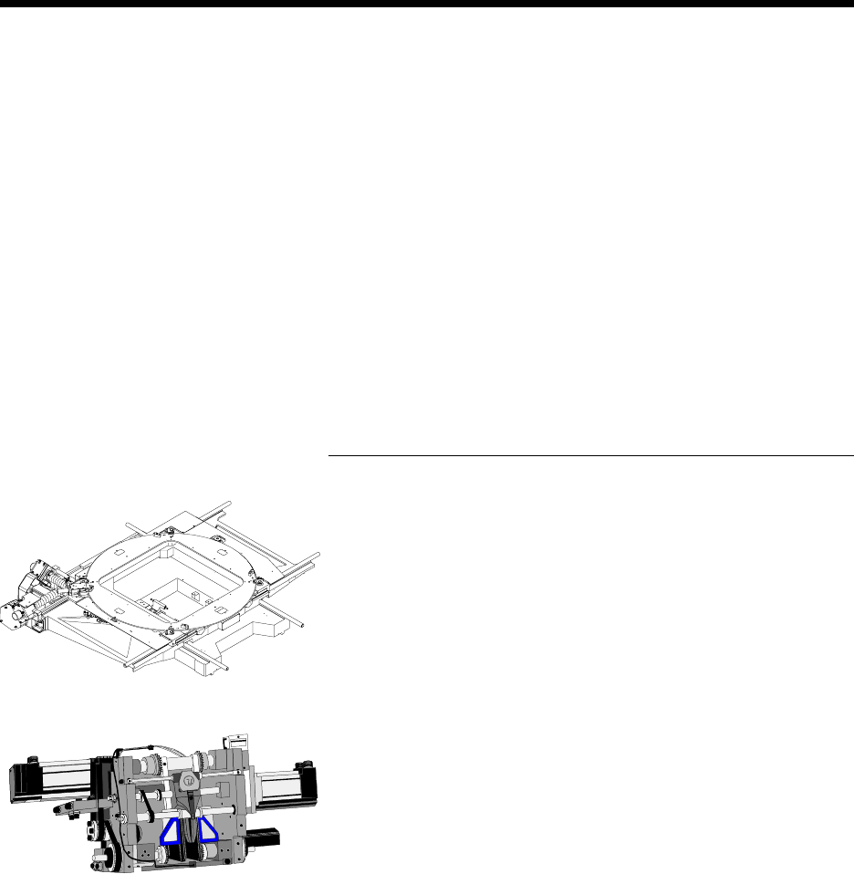
Machine Mechanical Systems
X-Y Positioning System
The X-Y positioning system locates the printed circuit board under
the insertion tooling and may be equipped with a rotary indexing table
that indexes in 90° increments, from 0° to 360° in a clockwise
rotation. When the machine is configured with automatic board
handling, the table can rotate a full 180° or 270° without 90° stops.
This rotary table is air motor driven under pattern program control
and requires less than one second to execute each 90° rotation.
Insertion Head
The insertion head includes the necessary tooling for cutting compo-
nents from the head chain, forming the leads, and inserting them into
the PCB, at rates up to 25,000 components per hour.
Close coupled software provides controlled acceleration/decelera-
tion and velocity during the insertion process for increased reliability
and reduced noise.
The machine handles varying component body diameters by soft-
ware selectable depth stops via the Advanced Product Editor and
based on component size, programmable in 0.03mm (0.001") incre-
ments, from 0mm to 5.49mm (0" - 0.216").
Minimum Hardware/software requirements to run the Vir-
tual P.C. (OS/2 and Windows) option:
Software requirements:
• Windows 98 (restrictions apply)
• Windows ME
• Windows NT 4
• Windows 2000
• Windows XP
Hardware requirements:
• 256 MB memory
• 500 MHz or better Pentium class processor with level 2 cache
or better