6241f - 第20页
Page 12 GS-394-02 Scrap Lead Removal Scrap leads remaining in the head chain clips after component insertion are released automatically in the chain-to-chain cabinet before the chain returns to pick up new components. Sc…
Page 11GS-394-02
Insertion Hole Span
Both the head and clinch component insertion spans are automati-
cally calculated by the Advanced Product Editor, and based on lead
diameter and center to center hole spacing on the PC board.
Insertion hole span range is dependent upon head tooling configura-
tion.
Refer to Technical Specifications section for insertion hole span
ranges.
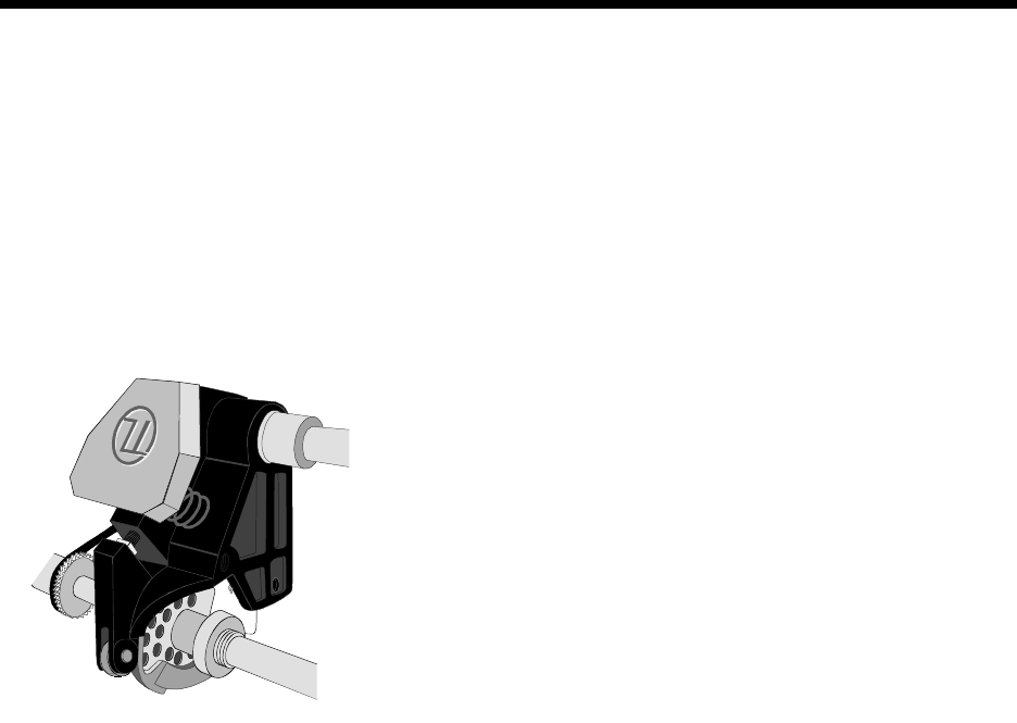
Component Centering
Before insertion into the PCB, each component in the head chain is
accurately centered. Component centering is achieved by using a
servo driven cam system. The unique cam design allows both rapid
positioning of the centering fingers and precise centering action prior
to component insertion.
The centering device is belt driven by the tooling insertion axis, and
requires no air cylinders or sensors to operate. Only four simple set-
up adjustments are required.
Insertion Tooling
Universal offers two types of insertion tooling: standard and 5mm.
Tooling type is selected to provide optimum performance depending
upon board density (footprint), component lead wire size and
material, component body size, hole spans, and board configurations.
Compared to pre Generation 8 machines, the current tooling has
been designed for improved reliability, longer tooling life, and better
handling of bent lead component input. This tooling incorporates
generous amounts of carbide inserts and has increased cross-
sections for greater robustness.
Refer to Technical Specifications section for tooling specifications.
Above board clearance beneath the retracted tooling is approxi-
mately 20.32mm (0.800"). See Tooling Footprints and Component
Clearances sections relating to tooling footprints.
Page 12 GS-394-02
Scrap Lead Removal
Scrap leads remaining in the head chain clips after component
insertion are released automatically in the chain-to-chain cabinet
before the chain returns to pick up new components. Scrap drops
into a waste basket in the left bottom side of the transfer cabinet.
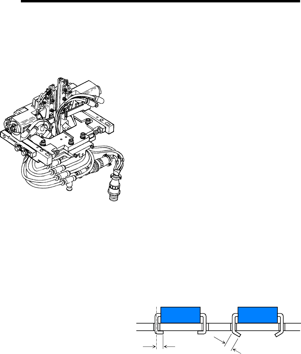
Cut and Clinch
Once a component has been inserted into the PCB, the cut and
clinch mechanism clinches the two leads to a repeatable angle, and
then cuts the leads to an adjustable length. The cut and clinch
contains a servo-driven rocker/slide up/down mechanism and pro-
vides PC board support during the insertion cycle, then trims and
clinches the component leads to the underside of the PC board with
a pneumatic actuated cutter.
Two-step operation allows the clinch to return to its lowest position
during a table rotation and only half the distance during the insertion
process, saving time and wear on mechanical parts. Insertion span
is servo controlled over the same span as the insertion head, and left
and right anvils are coupled.
Clinch angle is inward and may be adjusted over a range from 0º to
45º from the PC board bottomside. Clinch lead length is adjustable
from 1.28mm (0.050") to 1.80mm (0.071"). Lead length is measured
from the center of the insertion hole to the end of the lead. The
tolerance on the lead length is ±0.29mm (0.011").
The VCD/Sequencer 8 cut and clinch uses a dual lead continuity
check to verify component insertion. The failure of either lead to
pass through the PC board and be clinched will generate an insert
error and cause the machine to stop.
Clinch
Length
Clinch
Length
Finished Clinch Example
0° Clinch 45° Clinch
Page 13GS-394-02
Chain-to-Chain Transfer
The chain-to-chain system transfers components from the sequenc-
ing chain to the insertion head chain. The design minimizes set-ups
and adjustments and uses a servo motor belt drive system, with
position feedback encoder, to provide a highly reliable component
transfer. Automatic belt tensioning assures that belts are properly
adjusted.
Low Part Sensing/Display
The low part sensing feature provides the operator with a visual
alarm display whenever any input tape station nears empty within
each add-on module. Each input station contains a roller-type sensor
flag assembly that interrupts a light beam when the tape runs out.
The main machine tower light illuminates, and an audible alarm is
sounded, when a low part condition is sensed. The tower light is
reset when a new reel or box of components is installed and the
sensor is reset on top of the new tape. In addition, an error message
is displayed on the monitor to inform the operator of the location of
the low part condition.
Scrap Tape Removal
The two scrap tapes from each dispense head drop down into the
removable scrap bins located beneath the dispense heads. These
scrap bins are open on both ends so that tape can be swept through
all add-on modules and removed in one location.
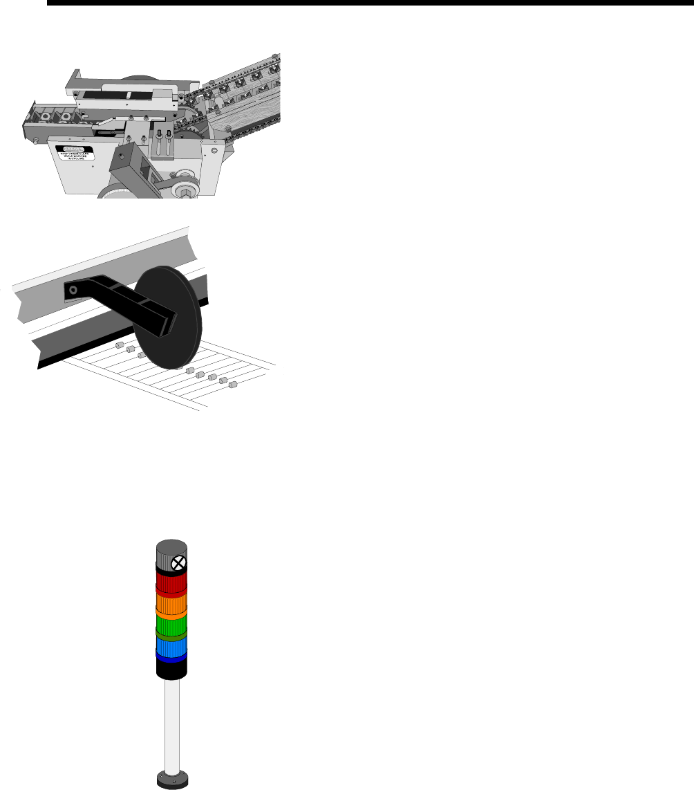
Machine Status Light/Audible Alarm
The machine status light/audible alarm indicates the status of
machine operation. Each of the lights are user configurable via the
machine software.
• Red
• Yellow
• Green
• Blue
• Audible alarm