6241f - 第25页
Page 17 GS-394-02 28 5m m (11") 350m m (14") Card bo ard Drum Wire Input — Quality of jumper wire input is critical to reliable machine operation. The wire must be able to be drawn from its package without tang…
Page 16 GS-394-02
Expanded Range Component Verifier
The Expanded Range Component Verifier, Model 2864A, provides
for the on-line verification of component value and polarity. It is
capable of verifying most axial leaded components including capaci-
tors (value only), refer to GS-167, "Expanded Range Component
Verifier," for specific component values. The verifier station is
located on the insertion head assembly. Verification parameters are
entered as part of the pattern program commands. The verifier halts
the machine for components failing verification and allows them to
be replaced at the manual load/replace station of the insertion head
if the REPAIR function is selected.
Using the verifier option greatly reduces the possibility of inserting
defective, out-of-sequence, or incorrectly oriented components.
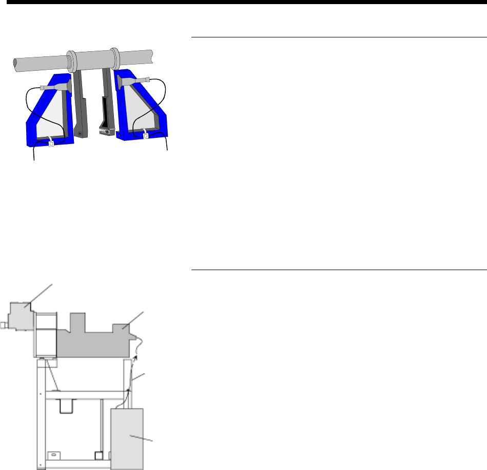
Jumper Wire Dispenser System
A jumper wire dispensing head and feeder assembly included in this
option processes jumper wires from a continuous spool of wire,
eliminating dispensing from reels of previously taped and reeled
jumper wires. It dispenses accurate lengths of cut wire and conve-
niently changes to various wire gages and lengths. It is available as
a factory installed option and as a retrofit kit. A maximum of two
Jumper Wire Dispenser Systems may be installed in any
machine configuration.
The Jumper Wire Dispenser System operates by drawing wire from
bulk input; a cardboard drum package works best. The wire feeder
assembly straightens and then feeds the wire to the dispensing head.
Pattern program control cycles the dispensing head, cutting a length
of wire from the continuous strand, and dispensing it onto the
sequencer chain.
Jumper Wire
Dispensing Head
Jumper
Wire
Feeder
Input
Jumper
Wire
Guide
Tube
Bulk
Wire
Input
Page 17GS-394-02
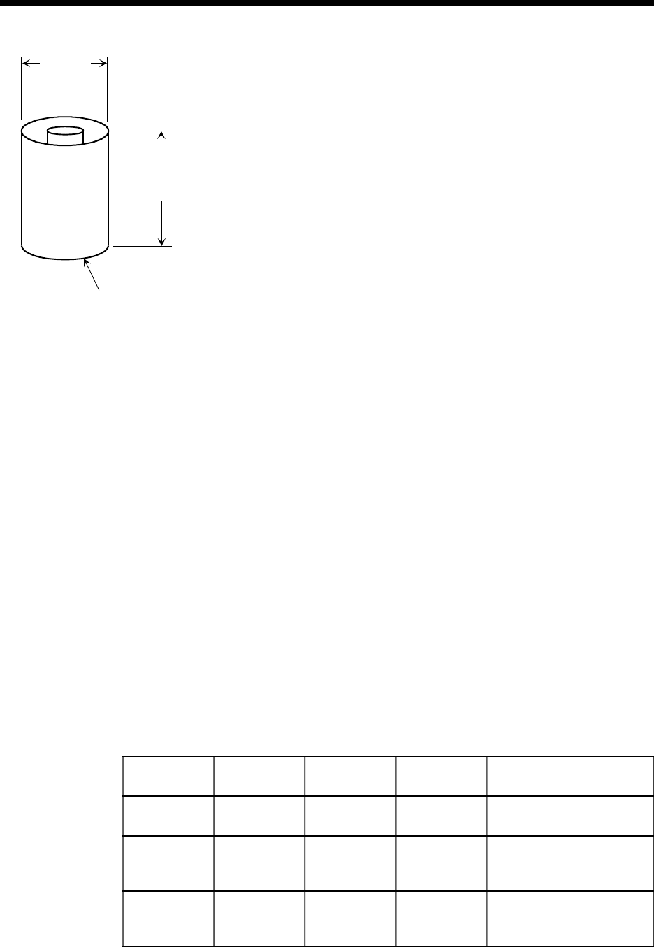
285mm
(11")
350mm
(14")
Cardboard
Drum
Wire Input — Quality of jumper wire input is critical to reliable
machine operation. The wire must be able to be drawn from its
package without tangling and without excessive drag. The
preferred package is a cardboard drum measuring 350mm (14")
high by 285mm (11") diameter which may be placed on the floor
next to the machine.
Wire is also available on reels, and the optional dereeler assem-
bly must be purchased to allow use of small reels up to 178mm
(7") diameter. There are some potential issues when using reel
type packaging:
• The optional reel holder will work with reels up to 178mm
(7") diameter. If a larger reel will be used, the wire must be
able to feed smoothly if the reel is placed directly on the
floor.
• Smaller reel packages require more frequent changeover.
• Some types of reel packages will not feed properly and
may not allow the machine to run at all.
The suggested source for wire input is Hitachi Cable America
Inc. (White Plains, NY; 1-800-394-0234). Specify part number
"1TPA 0.60***5BP". This part number indicates 0.60mm
diameter (0.024") solder coated copper wire in a 22 kilogram
(approx. 48 pound) cardboard drum package.
The Hitachi wire is also available through Universal's spare
parts division by ordering Universal part number 45126001.
Cut wire length — Class A: 50.80mm ±0.25mm (2.000" ±
0.010"), with thumbwheel increments of 0.10mm (0.004").
Wire diameter — 0.6mm (0.024") solder coated copper wire is
standard. The wire sizes below are tested with the expected
results listed. Consult a Universal Sales Engineer for details.
Wire
Diameter
Tensile
Strength
Maximum
Elongation
Insertion
Hole Span
Comments
0.6mm 27-35 kg/mm
2
4% 5mm-33mm Recommended for optimal
performance
0.5mm 27-35 kg/mm
2
4% 5mm-20mm Expect higher PPM when
insertion span increases to
21mm-33mm range
0.45mm 22-30 kg/mm
2
20% 5mm-20mm Expect higher PPM when
insertion span increases to
21mm-33mm range
Wire Specifications
Page 18 GS-394-02
Automatic Board Handling Configurations
The VCD/Sequencer 8 is available in several material handling
configurations (left-to-right, or right-to-left):
Magazine-to-Magazine (CE-compliant), with extra cost
covers.
Vacuum Bare Board-to-Magazine (not CE-compliant).
PCB Destacker-to-Magazine.
• Destacker on 29" Conveyor (not CE-compliant).
• Destacker on 44" Conveyor (not CE-compliant).
• Destacker on 58" Conveyor (CE-compliant) with extra cost
covers.
Magazine to PCB Destacker-to-Magazine.
• Destacker on 29" Conveyor (not CE-compliant).
• Destacker on 44" or 58" Conveyor. Input PCBs including
any installed components can not exceed 25.4mm (1")
thickness (CE-compliant with extra cost covers).
Internal Board Handling System (BHS) - Internal BHS for inline
systems integration is also available. Transfer direction may be
specified when ordering the machine. The front fixed rail is
standard and all operator PC board changeover adjustments are
readily accessible.
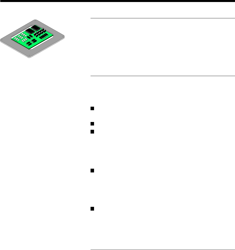
Rear Monitor
A rear monitor option is provided to allow operators and mainte-
nance personnel to view “on-screen” information from the back of
the machine. The rear monitor, which is identical to the front, is set
on a pivoting monitor arm attached to the top of the transfer cabinet.
The additional screen will aid operators in back of the machine by
displaying missing part head locations, as well as other machine
status messages. The monitor can also assist in maintenance
functions by displaying diagnostic I/O activity.
Workboard Holder
Workboard holders are required to accurately secure PC boards to
the rotary table during the insertion process when manual PCB load/
unload is being considered. Universal provides a wide range of
workboard holder products which can be ordered separately or with
a new machine purchase. When the machine is equipped with
internal BHS, a workboard holder is not required.