6241f - 第28页
Page 20 GS-394-02 Technical Specifications Input Specification The axial lead components prepared and taped to the requirements established in GS-061 “Lead Tape Reel Packaging of Axial Lead Components,” which is an adapt…

Page 19GS-394-02
Host Computer Interface Kit
This kit is used to interface VCD/Sequencer 8 with a Host computer
using the SECS/GEM Standard. The Generic Equipment Model
(GEM) Standard defines a standard implementation of the SECS II
(Semi Equipment Communications Standard 2) communications
interface for all semiconductor manufacturing equipment. See
SEMI International Standards document E30-93 for details. Note:
Requires customer’s Host computer to be compliant with SECS/
GEM standard SEMI E37, HSMS.
CE Non Pass Through Cover Package
• In normal run mode, front covers open when board is complete
to allow PCB unload/load.
• After operator changes the board, a button is pressed to close
the covers and reset the interlock and start button is pressed to
resume operation.
• The covers may be opened at any time by pressing the stop
button then the open cover button.
• The covers may be configured through software to open if an
error caused the machine to stop, i.e. missing part or misinsertion.
• Circuitry and software unique to CE NPT cover package
improves interlock recovery time after the covers have been
opened (interlocks violated) to load/unload the PC board.
• When interlock bypass key is switched to "maintenance mode",
air is removed from the cover air cylinders and the covers may
be opened and closed manually.
• Compatible with existing "stand alone" workboard holders.
Supporting Documents
GS-061 Lead Tape Reel Packaging of Axial Components,
Series 2500
GS-134 Workboard Holders, Series 6810
GS-354-01 Through Hole Design Guidelines
EIA RS-296-E Lead Taping of Components in Axial Configura-
tion for Automatic Insertion
GS-167 Expanded Range Component Verifier, Series 2860

Page 20 GS-394-02
Technical Specifications
Input Specification
The axial lead components prepared and taped to the requirements
established in GS-061 “Lead Tape Reel Packaging of Axial Lead
Components,” which is an adaptation of EIA standard RS-296-E,
may be processed by the VCD/Sequencer 8. The standard input for
this machine is Class I.
Class II input may be located in only eight designated stations per
add-on module, exclusive of the Jumper Wire option. (See table on
following page.)
Class III input is not recommended for use in this machine.
Input stations are designed to accept reel or ammo pack component
packages.
Page 21GS-394-02
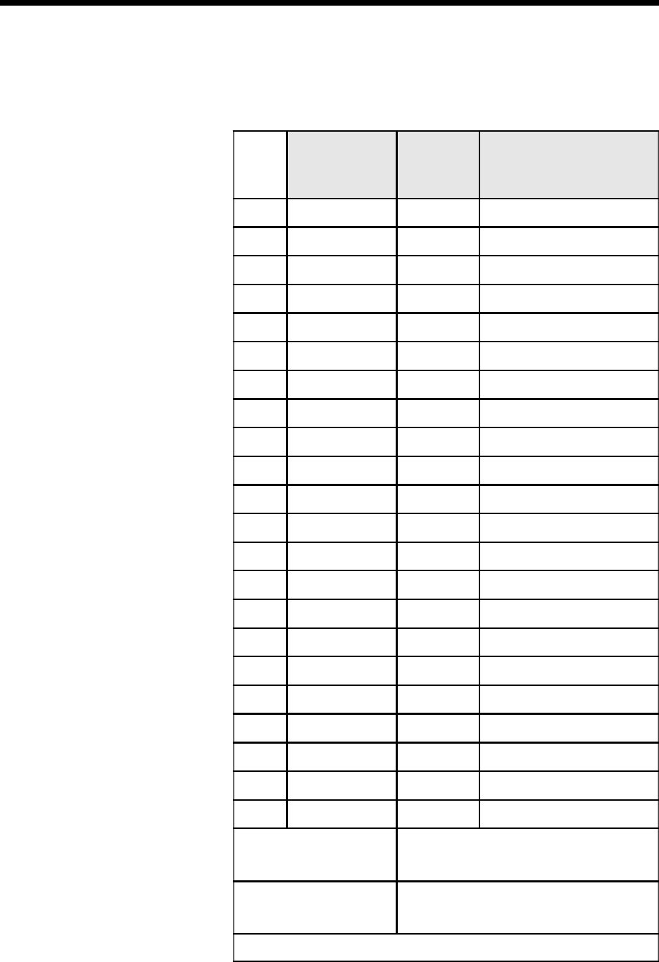
Sequencer Input Configuration for Each Add-On
Module
Location of Dispensing Stations by Component Class
Station
Class I
5.08mm (0.200")
& 10.16mm
(0.400") Pitch
Class II
5.08mm
(0.200")
Pitch*
Notes
1
9
2
9
3
99
Without Jumper Wire
3With Jumper Wire
4
9
5
99
If no Jumper Wire in Station 3
5
99
If Jumper Wire in Station 3
6
9
7
9
8
9
9
9
10
9
11
99
Any Combination
12
9
13
99
Any Combination
14
9
15
99
Any Combination
16
9
17
99
Any Combination
18
9
19
99
Any Combination
20
9
With Jumper Wire:
14 stations for Class I only
5 stations for Class I or II
1 station for Jumper Wire only
Without Jumper Wire:
13 stations for Class I only
5 stations for Class I or II
2 stations for Class I or II
*
10.16mm (0.400") pitch is not recommended.