6241f - 第33页
Page 25 GS-394-02 Recommended Component Clearances 1 A B C D C Standard and 5mm tooling Lead Diameter 0.38 (0.015) 0.81 (0.032) A Dimen sion 2 0.97 (0.038) 1.22 (0.048) B Dime nsion 1.14 (0.045) C Dime nsion 0.25 (0.010)…
Page 24 GS-394-02
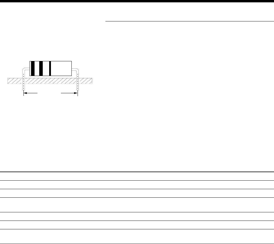
Component Body Length Considerations
After the tooling type and the variables have been determined from
the Insertion Tooling Specification table, the minimum allowable
hole span can be determined for a known body length.
Machine capabilities allow components to be inserted using the
minimum hole span formulas below. Due to body length variations,
it is recommended to design hole spans greater than the calculated
minimum.
Use the following formulas, depending on tooling type -- standard,
large lead, 5mm, or 5.5mm -- to calculate the minimum insertion hole
span for a known body length. The formulas apply to the body length
ranges shown and are based on a ±0.41mm (0.016") component
centering accuracy on the input tape. Component centering must
meet requirements stated in GS-061.
Minimum Insertion Hole Span Formulas for Maximum Body Lengths
Standard Tooling [Body Length Range: 0 to 15.75mm (0.620")]
Metric Formula: Minimum Hole Span = [(Component Body Length
1
x 1.112) + 2.36mm] - Lead Diameter
Inch Formula: Minimum Hole Span = [(Component Body Length
1
x 1.112) + 0.093"] - Lead Diameter
5mm Tooling [Body Length Range: 0 to 15.75mm (0.620")]
Metric Formula: Minimum Hole Span = [(Component Body Length
1
x 1.109) + 1.40mm] - Lead Diameter
Inch Formula: Minimum Hole Span = [(Component Body Length
1
x 1.109) + 0.055"] - Lead Diameter
1
Subtract an additional 0.41mm (0.016") from the maximum body length for non-symmetrically shaped
components.
HOLE SPAN
Page 25GS-394-02
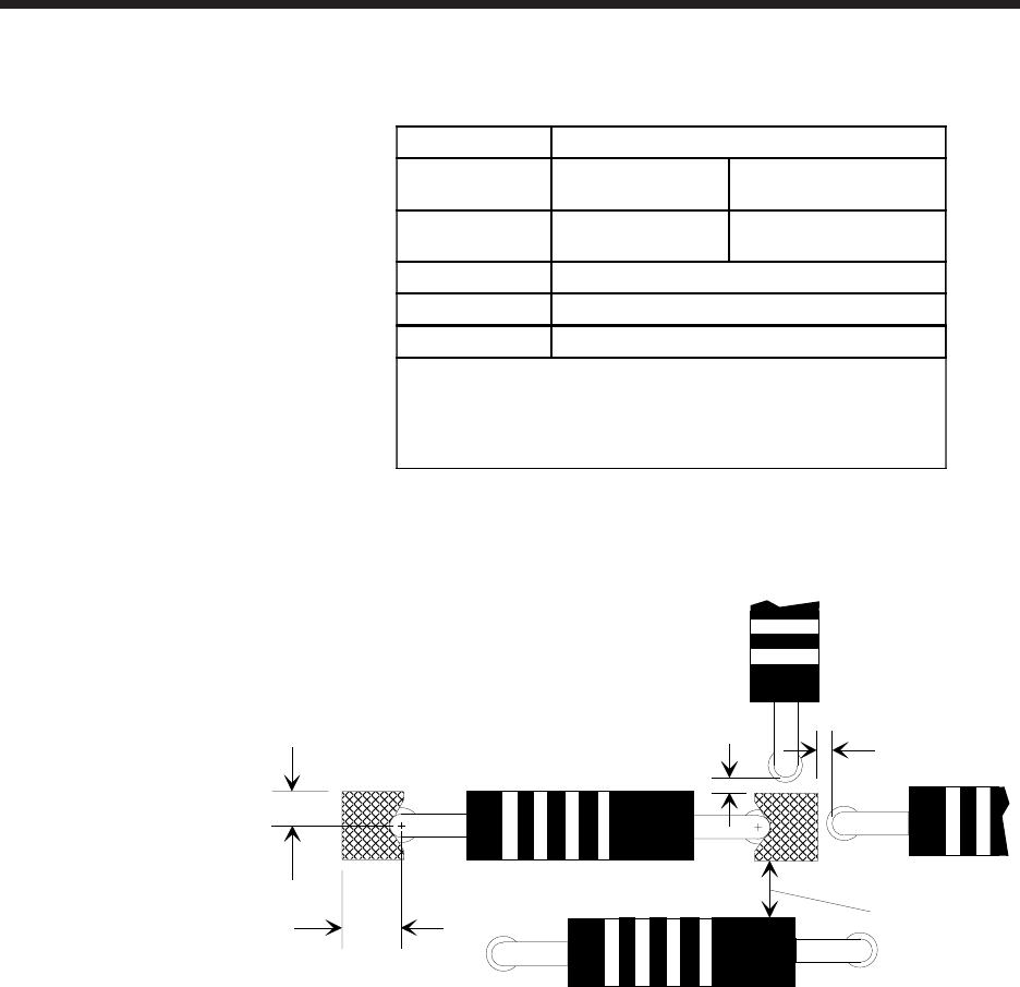
Recommended Component Clearances
1
A
B
C
D
C
Standard and 5mm tooling
Lead
Diameter
0.38
(0.015)
0.81
(0.032)
A Dimension
2
0.97
(0.038)
1.22
(0.048)
B Dimension
1.14 (0.045)
C Dimension
0.25 (0.010)
D Dimension
0.76 (0.030)
1
Dimensions are given in millimeters; inches are in
parentheses.
2
Dimension A is measured at the smallest possible footprint
for standard, and 5mm tooling.
See Tooling Footprints for related dimensions.
Page 26 GS-394-02
The table below provides tooling information for determining com-
ponent clearances relating to tooling footprints.
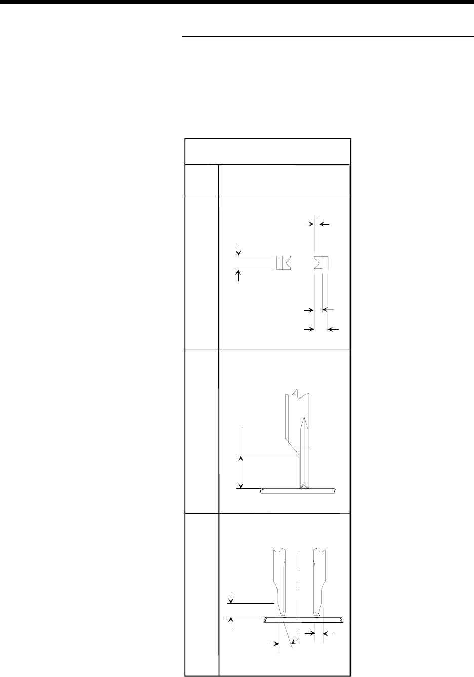
Insertion Tooling Footprint
6.43 (0.253)
Standard and 5mm
Tooling
Front View Side View Bottom View
Dimensions are in millimeters;
inch equivalents are bracketed.
0.48 (0.019)
2.29 (0.090)
1.27 (0.050)
2.29 (0.090)
3.81 (0.150)
1.27
(0.050)
15
o