6241f - 第34页
Page 26 GS-394-02 The table below provides tooling information for determining com- ponent clearances relating to tooling footprints. Insertion Tooling Footprint 6.43 ( 0.253 ) Standard a nd 5 mm Tool ing Front Vi ew Si …
Page 25GS-394-02
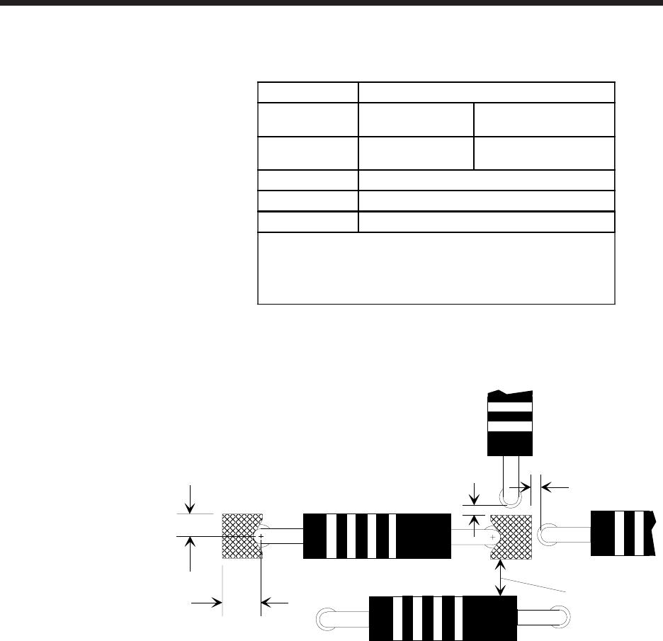
Recommended Component Clearances
1
A
B
C
D
C
Standard and 5mm tooling
Lead
Diameter
0.38
(0.015)
0.81
(0.032)
A Dimension
2
0.97
(0.038)
1.22
(0.048)
B Dimension
1.14 (0.045)
C Dimension
0.25 (0.010)
D Dimension
0.76 (0.030)
1
Dimensions are given in millimeters; inches are in
parentheses.
2
Dimension A is measured at the smallest possible footprint
for standard, and 5mm tooling.
See Tooling Footprints for related dimensions.
Page 26 GS-394-02
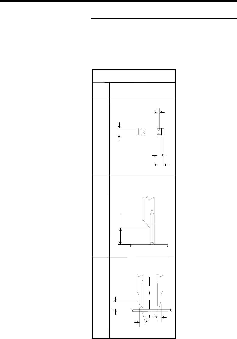
The table below provides tooling information for determining com-
ponent clearances relating to tooling footprints.
Insertion Tooling Footprint
6.43 (0.253)
Standard and 5mm
Tooling
Front View Side View Bottom View
Dimensions are in millimeters;
inch equivalents are bracketed.
0.48 (0.019)
2.29 (0.090)
1.27 (0.050)
2.29 (0.090)
3.81 (0.150)
1.27
(0.050)
15
o
Page 27GS-394-02
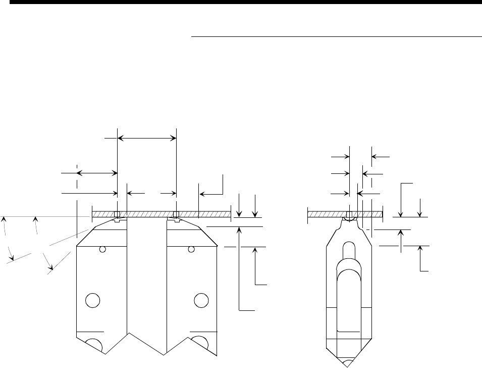
Cut and Clinch Footprint
6.15 (0.242)
3.61 (0.142)
2.11 (0.083)
7.98 (0.314)
3.58 (0.141)
8.13 (0.320)
2.72 (0.107)
6.10 (0.240)
11.51 (0.453)
2.62 (0.103)
Insertion
Center Distance
45°
23°
Dimensions are in millimeters;
inch equivalents are bracketed.