6241f - 第48页
A - 40 GS-394-02, Appendix: Automatic Board Handling Systems Board Handling System Specifications Minimum Maximum Transfer Height 1 1001.5 mm (39.43") to 1014.2 mm (39.93"), or 955.8 mm (37.63") to 968.5 m…

A - 39GS-394-02, Appendix: Automatic Board Handling Systems
Magazine- OR Destacker/Conveyor-to-Magazine Con-
figuration: Magazines containing partially populated PC boards
are placed on the input Elevator/Buffer (Loader) and the PC
boards are automatically transferred into the machine for
component insertion. In addition, a second input from a Destack
Loader, mounted on either a 736mm (29"), 1118mm (44"), or
1473mm (58") conveyor, can be placed in-line after the Eleva-
tor/Buffer. This permits the flexibility of loading unpopulated PC
boards from a stack, or populated PC boards from a magazine.
Once completed, the boards are unloaded into an output Eleva-
tor/Buffer (Unloader). Only the systems incorporating the
Destack Loader with the 1118mm (44") or 1473mm (58")
conveyor, and PC boards with installed components not
exceeding 25.4mm (1") thickness, are CE-compliant.
In-Line Configuration: Machines can be connected in-line
using the internal Board Handling System (BHS) and intercon-
necting conveyors. The BHS transfers two PC boards at a time:
an unpopulated board in, and a populated board out. All Board
Handling Systems are factory configurable for either left-to-
right or right-to-left direction. This configuration is CE-compli-
ant.
For detailed vacuum bare board loader and destacker specifica-
tions, see product information sheets for these products.
A - 40 GS-394-02, Appendix: Automatic Board Handling Systems
Board Handling System Specifications
Minimum Maximum
Transfer Height
1
1001.5 mm (39.43") to 1014.2 mm (39.93"), or
955.8 mm (37.63") to 968.5 mm (38.13")
Above Board — 20.3 mm (0.800"),
Clearance restricted by VCD/SEQ 8
Board Changeover Manual
Direction Select right-to-left or left-to-right.
Edge Clearance 5 mm (0.197") or 3 mm (0.118")
2
Fixed Edge Front
Locator Pins Front
Front Edge The front edge of the PC Board is fixed at
Distance 266.7mm (10.5") from the front of the machine.
(The back rail of the board handling is
adjustable.)
Transfer Time
3
2.5 seconds, maximum for 1007.9 mm (39.68")
transfer height (upper level)
5.5 seconds, maximum for 962.2 mm (37.88")
transfer height (lower level)
Notes:
1. Transfer height can be configured, and alters transfer time.
See transfer time specification.
2. Set at factory to 3 mm.
PC Board Specifications
Minimum Maximum
Length
1
x Width 102mm x 80mm 483mm x 406mm
(4" x 3.1")
2
(19" x 16")
2, 3
Length to Width >1:1 is recommended
Ratio
Thickness 0.8mm (0.032") 2.36mm (0.093")
Cutouts Continguous edges
Datum Hole 3.18mm (0.125")
2
6.35mm (0.25")
2
Diameter
Datum Hole See note 4.
Location
Weight 2.27kg (5 lbs.), maximum
Notes:
1. Length is in the direction of board flow.
2. Consult a Universal Sales Engineer for other than stated sizes.
3. Two datum holes are required. For ease of setup, the
workboard holder locator pins feature detents for PC board
datum holes located 3.5, 4.0, 5.0, 6.35, or 7.62 mm from the
front edge of the board. The maximum distance from the front
edge of the PC board to the center of the datum holes is
9.0mm.
4. A slot rather than a round hole is recommended for one locating
hole.
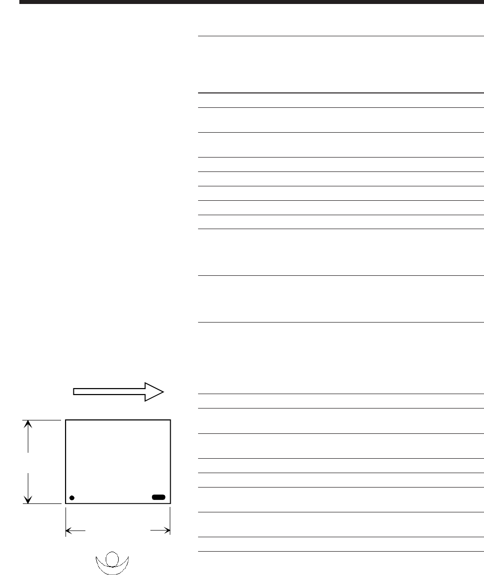
Operator
Technical Specifications for Internal
Board Handling System (BHS)
Min. 80 mm (3.1")
Max. 406 mm (16")
Min.100 mm (4")
Max. 483 mm (19")
Direction of Board Flow
See Note 4
A - 41GS-394-02, Appendix: Automatic Board Handling Systems
2. Dimensions are to the bottom of the 'V' groove in the former.
3. Dimension shown is for 3mm edge support. If using a 5mm edge support, add 2mm
Front at 180°
F
r
o
n
t
a
t
2
7
0
°
Front at 90°
A
B
CD
E
F
G
H
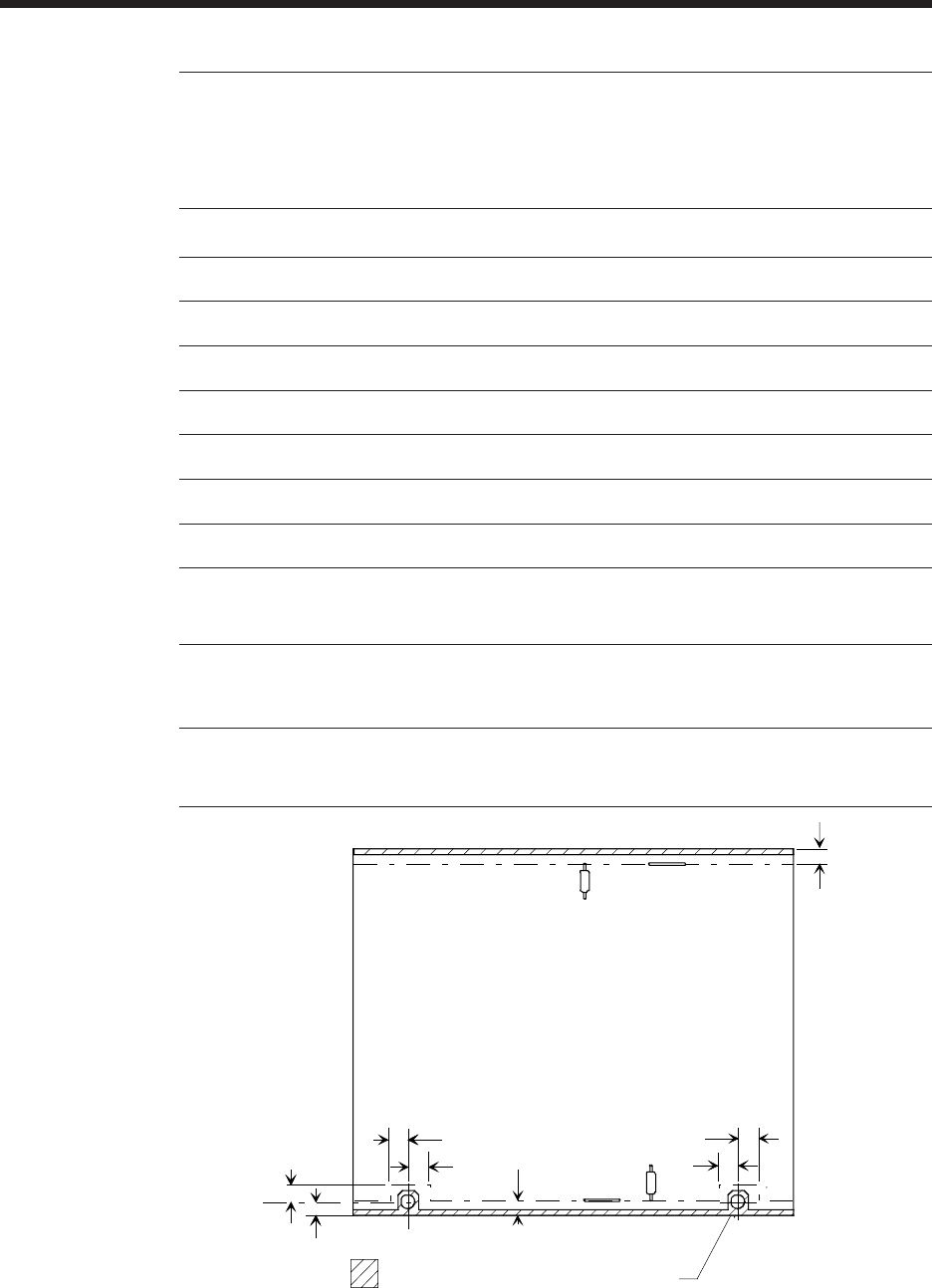
diameter J
X
Dimensions shown are minimum distances from
either the board edge or the tooling pin hole, to
either the standard tooling or the clinch.
3mm edge support
(Table Rotation Dimensions shown are for standard tooling)
0° 90° 180° 270°
A 5.99mm (0.236")
1
7.59mm (0.299")
2
9.27mm (0.365")
1
7.59mm (0.299")
2
B 7.09mm (0.279")
2
5.49mm (0.216")
1
7.09mm (0.279")
2
5.49mm (0.216")
1
C 7.09mm (0.279")
2
8.76mm (0.345")
1
7.09mm (0.279")
2
8.76mm (0.345")
1
D 7.09mm (0.279")
2
5.49mm (0.216")
1
7.09mm (0.279")
2
5.49mm (0.216")
1
E 7.09mm (0.279")
2
8.76mm (0.345")
1
7.09mm (0.279")
2
8.76mm (0.345")
1
F 5.33mm (0.210")
1, 3
5.38mm (0.212")
2, 3
5.33mm (0.210")
1, 3
5.38mm (0.212")
2, 3
G 5.33mm (0.210")
1, 3
5.38mm (0.212")
2, 3
5.33mm (0.210")
1, 3
5.38mm (0.212")
2, 3
H 3.17mm (0.125") minimum
6.35mm (0.250") recommended
7.62mm (0.300") maximum
J 3.17mm (0.125") minimum
3.96mm (0.156") recommended
6.35mm (0.250") maximum
1. Dimensions are to centerline of lead.
Workboard Clearances at Table Rotation Locations