6241f - 第50页
A - 42 GS-394-02, Appendix: Automatic Board Handling Systems Technical Specifications for Loader/ Unloader: Elevator/Buffer Configuration Buffer Changeover Time Magazine, 20 seconds PC Board The insertion machine determi…
A - 41GS-394-02, Appendix: Automatic Board Handling Systems
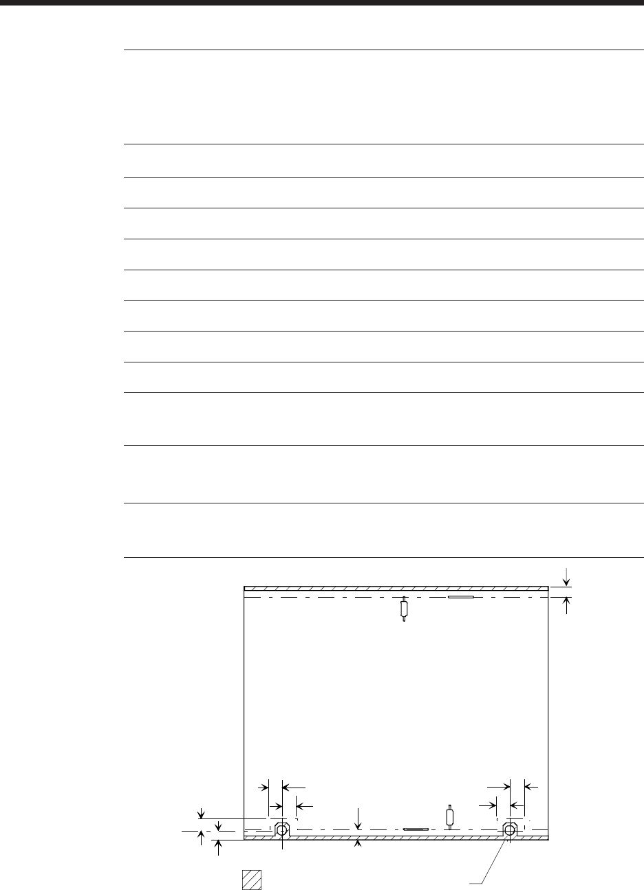
2. Dimensions are to the bottom of the 'V' groove in the former.
3. Dimension shown is for 3mm edge support. If using a 5mm edge support, add 2mm
Front at 180°
F
r
o
n
t
a
t
2
7
0
°
Front at 90°
A
B
CD
E
F
G
H
diameter J
X
Dimensions shown are minimum distances from
either the board edge or the tooling pin hole, to
either the standard tooling or the clinch.
3mm edge support
(Table Rotation Dimensions shown are for standard tooling)
0° 90° 180° 270°
A 5.99mm (0.236")
1
7.59mm (0.299")
2
9.27mm (0.365")
1
7.59mm (0.299")
2
B 7.09mm (0.279")
2
5.49mm (0.216")
1
7.09mm (0.279")
2
5.49mm (0.216")
1
C 7.09mm (0.279")
2
8.76mm (0.345")
1
7.09mm (0.279")
2
8.76mm (0.345")
1
D 7.09mm (0.279")
2
5.49mm (0.216")
1
7.09mm (0.279")
2
5.49mm (0.216")
1
E 7.09mm (0.279")
2
8.76mm (0.345")
1
7.09mm (0.279")
2
8.76mm (0.345")
1
F 5.33mm (0.210")
1, 3
5.38mm (0.212")
2, 3
5.33mm (0.210")
1, 3
5.38mm (0.212")
2, 3
G 5.33mm (0.210")
1, 3
5.38mm (0.212")
2, 3
5.33mm (0.210")
1, 3
5.38mm (0.212")
2, 3
H 3.17mm (0.125") minimum
6.35mm (0.250") recommended
7.62mm (0.300") maximum
J 3.17mm (0.125") minimum
3.96mm (0.156") recommended
6.35mm (0.250") maximum
1. Dimensions are to centerline of lead.
Workboard Clearances at Table Rotation Locations
A - 42 GS-394-02, Appendix: Automatic Board Handling Systems
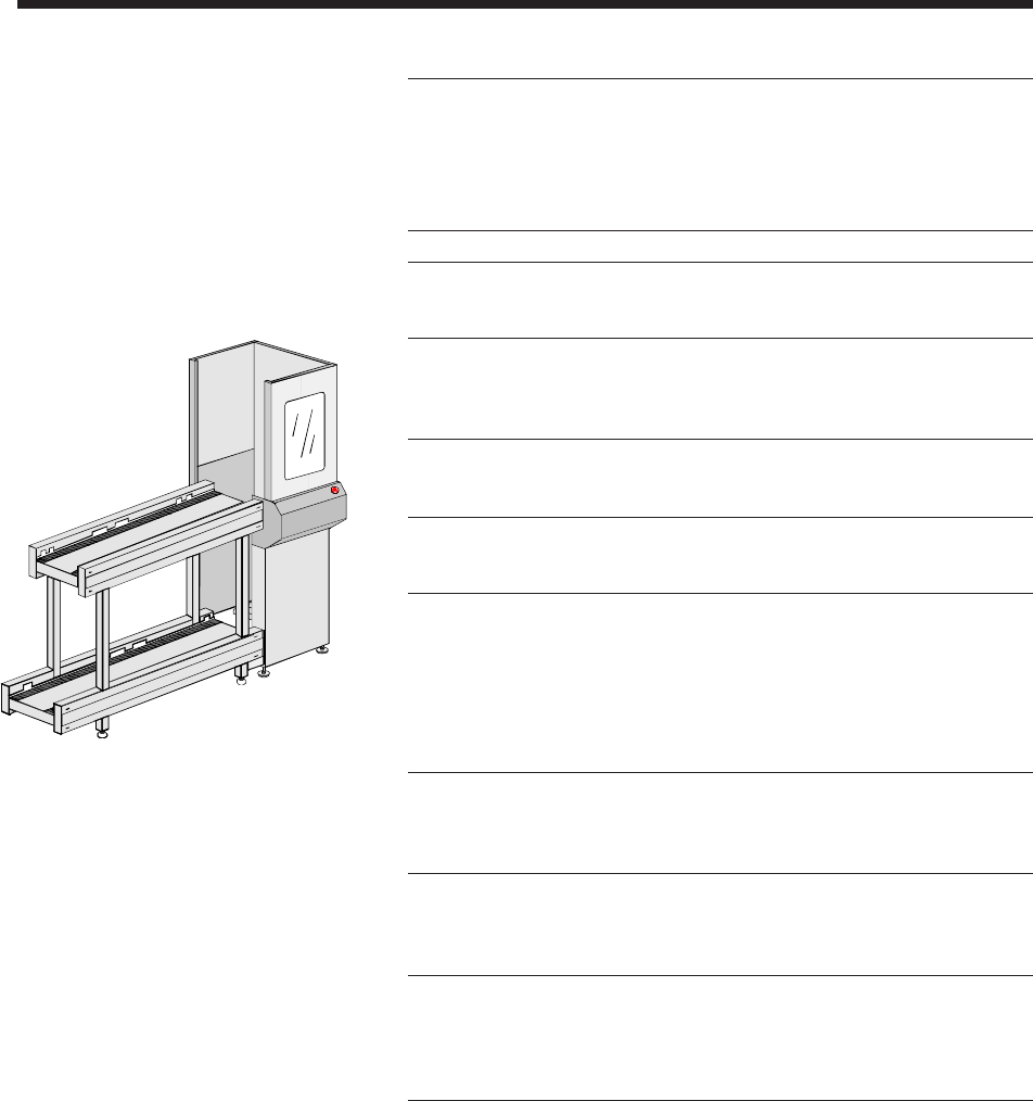
Technical Specifications for Loader/
Unloader: Elevator/Buffer Configuration
Buffer
Changeover Time Magazine, 20 seconds
PC Board The insertion machine determines board size.
Magazine Elevators
Magazine Elevator Controlled through insertion machine software.
Power and air are supplied through the insertion
machine. Elevators are equipped with
emergency stops.
Elevator Length Depth Height
Dimensions 635mm (25") 838mm (33") 1,835mm
(72")
Magazine Input/Output Buffers
Buffer The Buffer accomodates 2 magazines (in and
out) that are up to 533mm (21") in length each.
Buffers are available either with
CE-compliant Buffer covers or without the
covers. Covers must be affixed to the Buffers in
order for the Buffers to be CE-compliant.
Buffer Length Depth Height
Dimensions
With Full Covers 1,270mm 546mm 1,835mm
(CE-compliant) (50") (22") (72")
Buffer Length Depth Height
Dimensions
Without Covers 1,270mm 546mm 1,095mm
(Not CE-compliant) (50") (22") (43")
Magazine Transfer Upper level magazine transfer height is
Height 1,056mm (42").
Lower level Magazine transfer height
is 292mm (12").
A - 43GS-394-02, Appendix: Automatic Board Handling Systems
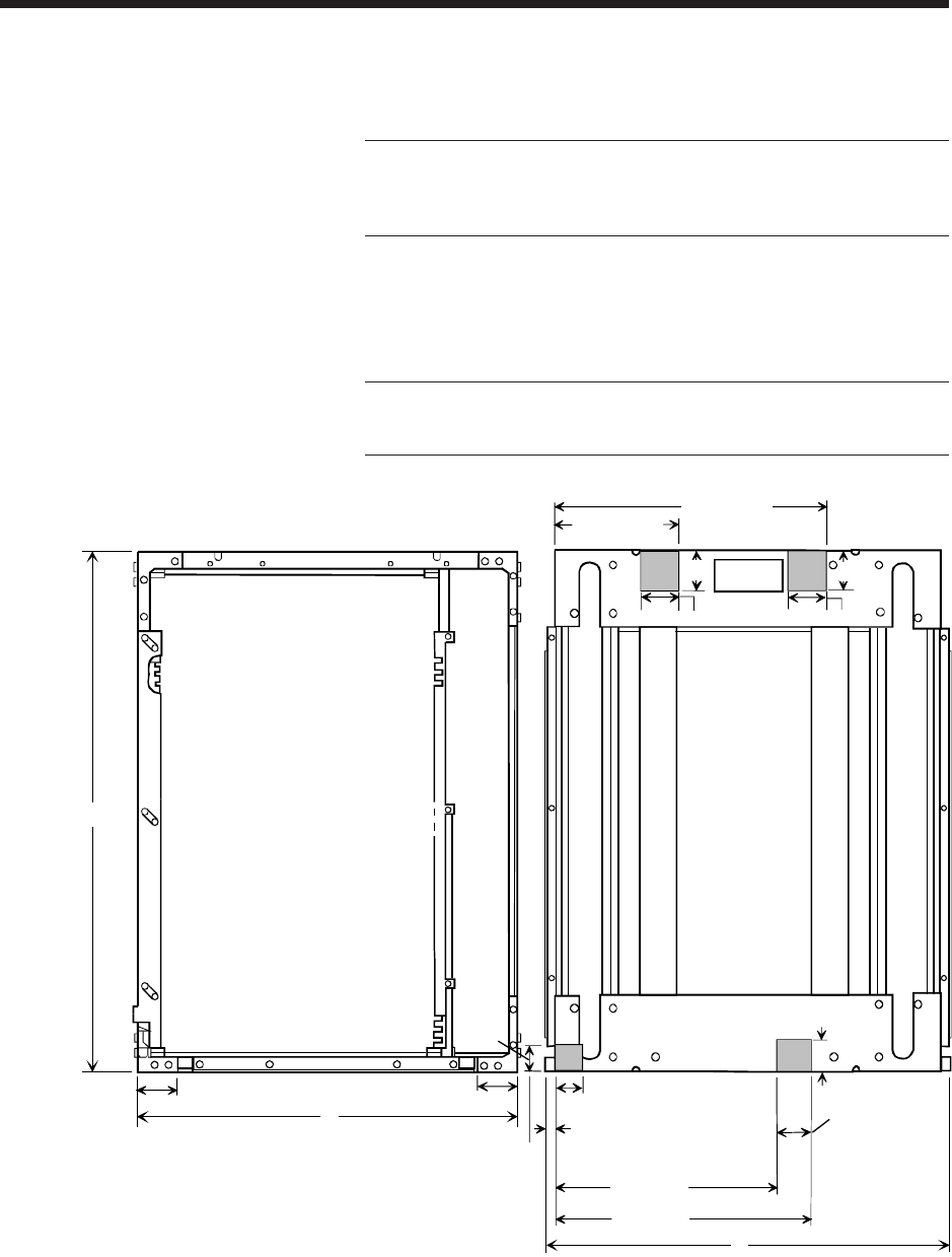
Magazine Specifications for use in
Elevator Buffer System
Maximum 45kg (100lbs) for PC boards plus magazines.
Magazine Weight Compatible with most commonly-used
magazines. Consult a Universal Sales
Engineer.
Maximum Magazine Maximum Maximum Maximum Maximum
Dimensions Length (B) Depth (A) Height (C) Weight
(including
PC boards)
533mm 460mm 606mm 45kg
(21") (18") (24") (100lbs)
Magazine If magazines have gates that must be
Gate Control opened by the machine, a sample magazine
and a request for quote must be submitted.
SIDE VIEW
END VIEW
B
A
MAGAZINE VIEWS
C
187.325mm
(7.375")
44.45 mm (1.75")
441.325mm
(13.375")
25.4mm
(1.00")
234.95mm
(9.25")
292.10mm
(11.50")
28.575mm
(1.125")
25.4mm
(1.00")
25.4mm
(1.00")
7.9375mm
(.3125")
25.4mm
(1.00")
187.325mm
(7.37")
44.45 mm (1.75")
44.45 mm
(1.75")
44.45 mm
(1.75")
25.4 mm
(1.00")
Note: Highlighted area must be solid to allow
detection and registration.