1745894799217463.pdf
IES2300SL with Fiber - Port Series Layer 2 Unmana ged Industr ial Ethernet Sw itch Quick Inst allation Guide 3onedata C o., Ltd. Address: 3/B, Zone 1, Baiwa ngxin High T echnology Industrial Park , Xili, Nanshan District…
IES2300SL with Fiber-Port Series
Layer 2 Unmanaged Industrial
Ethernet Switch
Quick Installation Guide
3onedata Co., Ltd.
Address:
3/B, Zone 1, Baiwangxin High Technology
Industrial Park, Xili, Nanshan District,
Shenzhen
Website:
www.3onedata.com
Tel:
+86 0755-26702688
Fax:
+86 0755-26703485
【Package Checklist】
Please check the integrity of package and accessories while
first using the switch.
1. Industrial Ethernet switch
2. DIN-Rail mounting attachment
3. Warranty card
4. Certificate
If any of these items are damaged or lost, please contact our
company or dealers, we will solve it ASAP.
【Product Overview】
This series product is a Gigabit unmanaged DIN-Rail
industrial Ethernet switch. For convenience, the products of
this series adopt the following number on the left in this guide,
please confirm the number of your product:
Model I. IES2300SL-4GT2GS-2LV (4 Gigabit copper ports +
2 Gigabit SFP slots, 12~60VDC redundant power
supply).
Model II. IES2300SL-8GT2GS-2LV (8 Gigabit copper ports +
2 Gigabit SFP slots, 12~60VDC redundant power
supply).
Model III. IES2300SL-8GP2GS-2LV (8 Gigabit PoE ports + 2
Gigabit SFP slots, 44~57VDC redundant power
supply).
Model IV. IES2300SL-16GT2GS-2LV (16 Gigabit copper ports
+ 2 Gigabit SFP slots, 12~60VDC redundant power
supply).
Model V. IES2300SL-16GP2GS-2LV (16 Gigabit PoE copper
ports + 2 Gigabit SFP slots, 44~57VDC redundant
power supply).
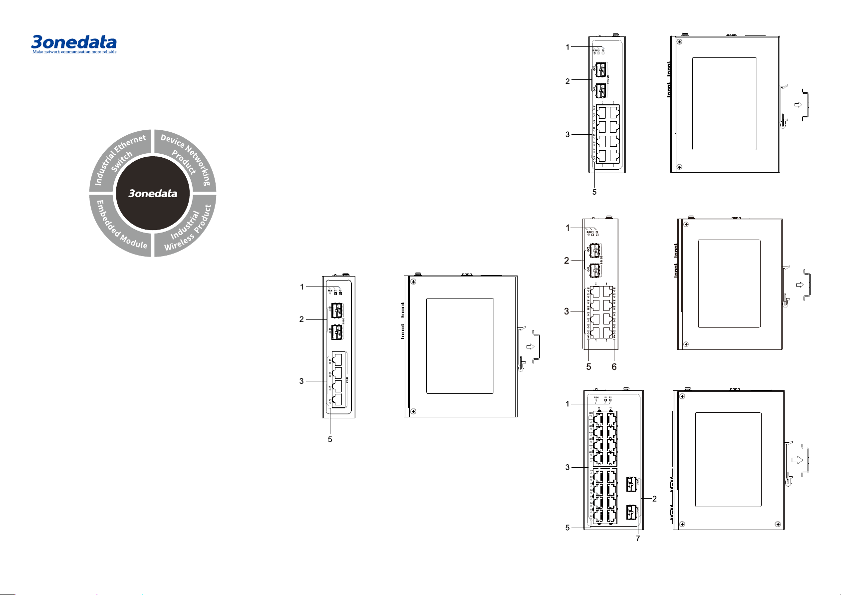
【Panel Design】
Main view and right view
Model I
Model II
Model III
Model IV
Model V
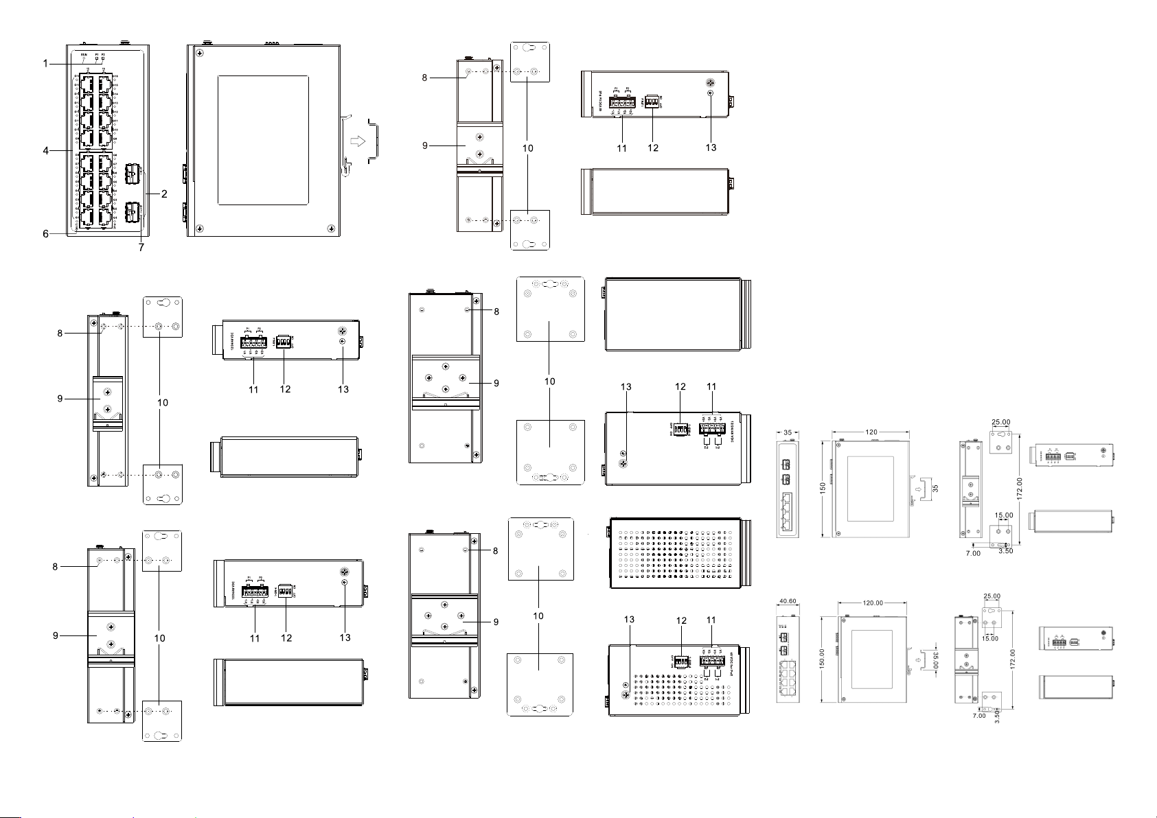
Rear view, top view and bottom view
Model I
Model II
Model III
Model IV
Model V
1. Indicators, from left to right are:
- Running indicator (RUN)
- Power supply indicator (P1)
- Power supply indicator (P2)
2. 1000Base-X Gigabit SFP slot (G6-G5, G10-G9,
G18-G17)
3. 10/100/1000Base-T(X) Gigabit copper ports
(G4/G8/G16-G1)
4. 10/100/1000Base-T(X) Gigabit PoE copper port
(G16-G1)
5. Ethernet port indicator (G6/G10/G16-G1)
6. PoE indicator (G16-G1)
7. SFP interface indicator (G18-G17)
8. Wall-mounting location hole
9. DIN-Rail mounting kit
10. Wall-mounting panel (additional purchase required)
11. Power input terminal (P1-P2)
12. DIP switch
13. Grounding screw (M4)
【Mounting Dimension】
Unit: mm
Model I
Model II, III
Model IV, V
Note:
Model II and III have the same dimensions.
Model IV and V have the same dimensions.
The wall-mounting panel at the right side of the above
figure is an optional attachment, not standard; DIN-Rail
kit is standard.
Notice Before Mounting:
Don't place or install the device in area near water or
moisture, keep the relative humidity of the device
surrounding between 5%~95% without condensation.
Before powering on the device, check the power
specifications supported by the device to prevent device
damage due to overvoltage.
The device surface temperature is high after running;
please don't directly contact to avoid scalding.
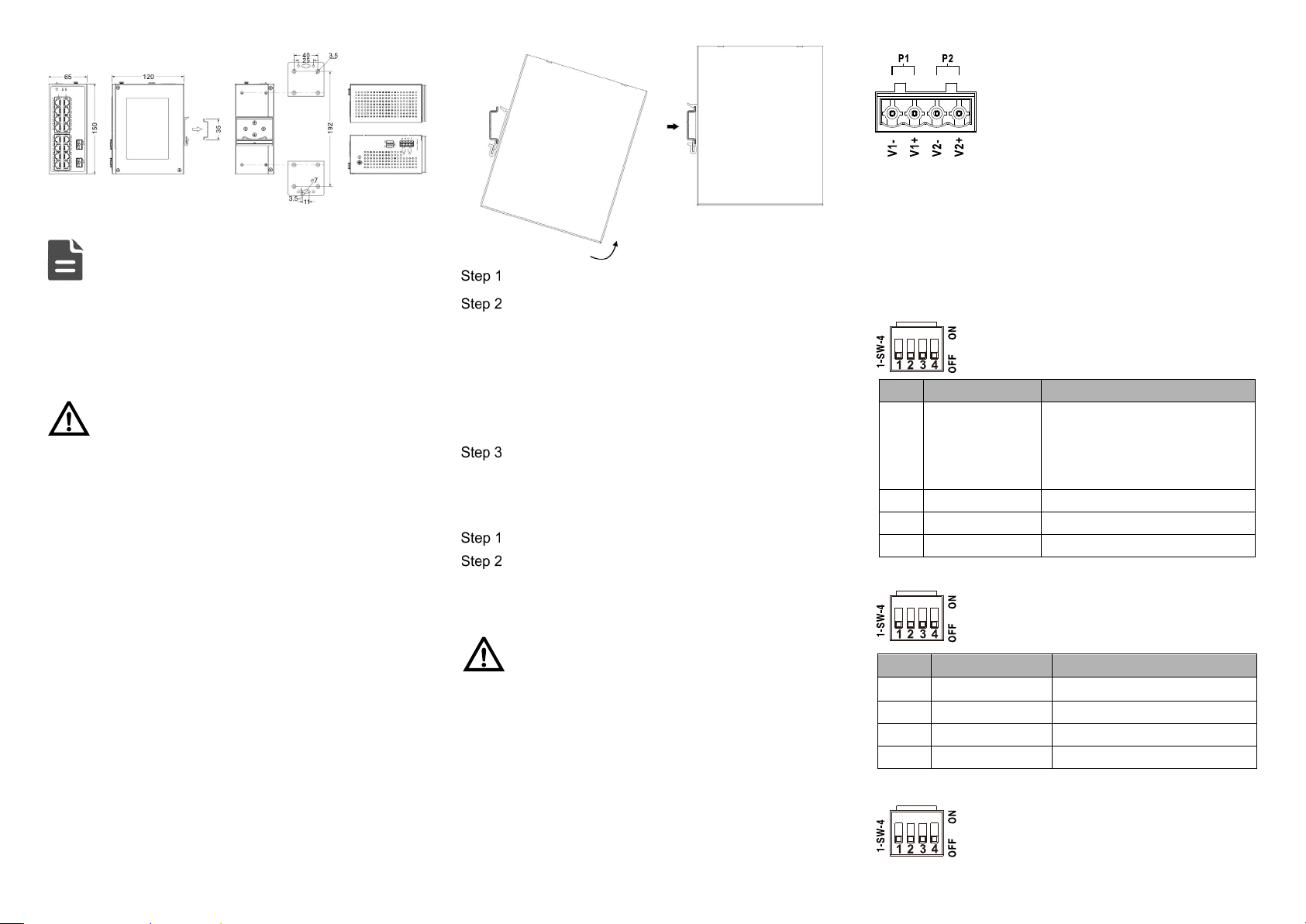
【DIN-Rail Mounting】
The product adopts 35mm standard DIN-Rail mounting which
is suitable for most industrial scenes, mounting steps are as
follows:
Check if the DIN-Rail mounting kit is installed firmly.
Insert the bottom of DIN-Rail mounting kit (one side
with spring support) into DIN-Rail, and then insert
the top into DIN-Rail.
Tips:
Insert a little to the bottom, lift upward and then insert
to the top.
Check and confirm the product is firmly installed on
DIN-Rail, then mounting ends.
【Disassembling DIN-Rail】
Power off the device.
After lifting the device upward slightly, first shift out
the top of DIN-Rail mounting kit, and then shift out
the bottom of DIN-Rail, disassembling ends.
Notice Before Powering on:
Power ON operation: First insert the power supply
terminal block into the device power supply interface,
and then plug the power supply plug and power on.
Power OFF operation: First, remove the power plug,
then remove the wiring section of terminal block. Please
pay attention to the above operation sequence.
【Power Supply Connection】
Support P1, P2 dual power redundancy, and adopt 4-pin
5.08mm pitch terminals. The power input supports 1 power
supply alone or 2 power supply at the same
time; When two power supply input at the
same time, it supports redundant backup of
power supply. If one power supply fails, the
device can still work normally without
interruption. Power supply supports
anti-reverse connection, which cannot power the device but
won’t damage it when it's reversely connected. The pin
definitions of power supply are shown as follows: The power
input range for Model I, II, and IV is 12-60VDC, while the
power input range for Model III and V is 44-57VDC.
【Model I DIP Switch Settings】
Provide 4 pins DIP switch for function settings,
where "ON" is enable valid terminal.
DIP switch definitions are as follows:
No.
Definition
Operation
1 Restore Factory
Settings
Set the DIP switch to ON, hold
for more than 1 second, and
then dial back to restart the
device.
2
Reserved
—
3
Reserved
―
4
Reserved
―
【Model II, III DIP Switch Settings】
Provide 4-pin DIP switch for function setting,
“ON" is enable valid terminal. DIP switch
definitions are as follows:
No.
Definition
Operation
1 Forced 100M Set the DIP to ON
2
Storm Control
Set the DIP to ON
3
VLAN
Set the DIP to ON
4
Flow control
Set the DIP to ON
【Model IV, V DIP Switch Settings】
Provide 4 pins DIP switch for function settings,
where "ON" is enable valid terminal. DIP
switches definition as follows: