1745894799217463.pdf - 第4页
No. Definition Operation 1 Reboot Set the code to ON, then set it back. 2 Reserved — 3 Reserved — 4 Reserved — 【 Checking LED I ndicator 】 Provide LED i ndicators to monit or its operat ing status, whic h has simplifi ed…
Model V
Rear view, top view and bottom view
Model I
Model II
Model III
Model IV
Model V
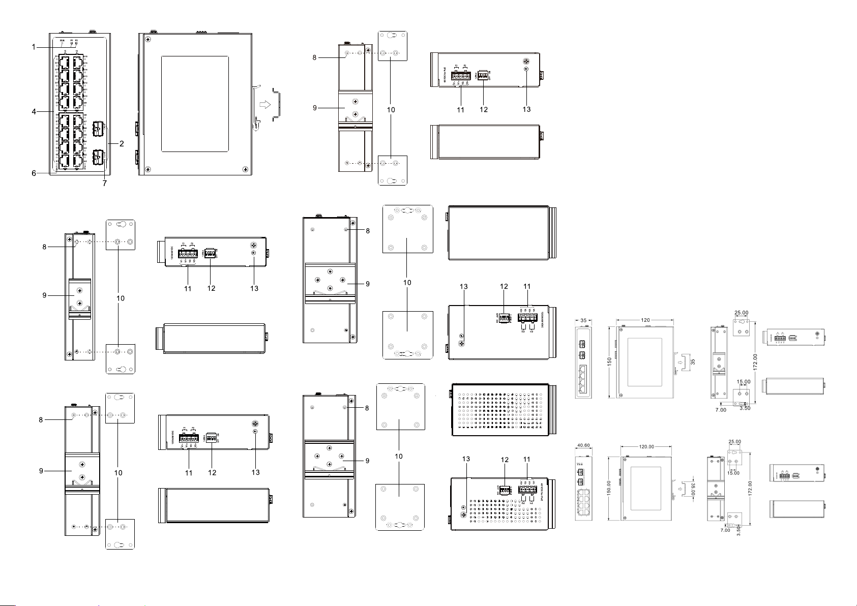
1. Indicators, from left to right are:
- Running indicator (RUN)
- Power supply indicator (P1)
- Power supply indicator (P2)
2. 1000Base-X Gigabit SFP slot (G6-G5, G10-G9,
G18-G17)
3. 10/100/1000Base-T(X) Gigabit copper ports
(G4/G8/G16-G1)
4. 10/100/1000Base-T(X) Gigabit PoE copper port
(G16-G1)
5. Ethernet port indicator (G6/G10/G16-G1)
6. PoE indicator (G16-G1)
7. SFP interface indicator (G18-G17)
8. Wall-mounting location hole
9. DIN-Rail mounting kit
10. Wall-mounting panel (additional purchase required)
11. Power input terminal (P1-P2)
12. DIP switch
13. Grounding screw (M4)
【Mounting Dimension】
Unit: mm
Model I
Model II, III
Model IV, V
Note:
Model II and III have the same dimensions.
Model IV and V have the same dimensions.
The wall-mounting panel at the right side of the above
figure is an optional attachment, not standard; DIN-Rail
kit is standard.
Notice Before Mounting:
Don't place or install the device in area near water or
moisture, keep the relative humidity of the device
surrounding between 5%~95% without condensation.
Before powering on the device, check the power
specifications supported by the device to prevent device
damage due to overvoltage.
The device surface temperature is high after running;
please don't directly contact to avoid scalding.
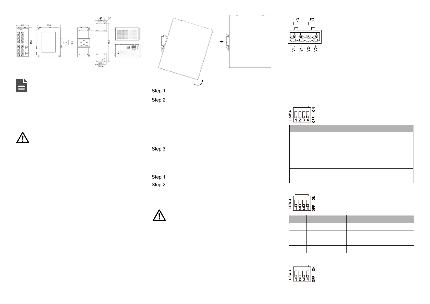
【DIN-Rail Mounting】
The product adopts 35mm standard DIN-Rail mounting which
is suitable for most industrial scenes, mounting steps are as
follows:
Check if the DIN-Rail mounting kit is installed firmly.
Insert the bottom of DIN-Rail mounting kit (one side
with spring support) into DIN-Rail, and then insert
the top into DIN-Rail.
Tips:
Insert a little to the bottom, lift upward and then insert
to the top.
Check and confirm the product is firmly installed on
DIN-Rail, then mounting ends.
【Disassembling DIN-Rail】
Power off the device.
After lifting the device upward slightly, first shift out
the top of DIN-Rail mounting kit, and then shift out
the bottom of DIN-Rail, disassembling ends.
Notice Before Powering on:
Power ON operation: First insert the power supply
terminal block into the device power supply interface,
and then plug the power supply plug and power on.
Power OFF operation: First, remove the power plug,
then remove the wiring section of terminal block. Please
pay attention to the above operation sequence.
【Power Supply Connection】
Support P1, P2 dual power redundancy, and adopt 4-pin
5.08mm pitch terminals. The power input supports 1 power
supply alone or 2 power supply at the same
time; When two power supply input at the
same time, it supports redundant backup of
power supply. If one power supply fails, the
device can still work normally without
interruption. Power supply supports
anti-reverse connection, which cannot power the device but
won’t damage it when it's reversely connected. The pin
definitions of power supply are shown as follows: The power
input range for Model I, II, and IV is 12-60VDC, while the
power input range for Model III and V is 44-57VDC.
【Model I DIP Switch Settings】
Provide 4 pins DIP switch for function settings,
where "ON" is enable valid terminal.
DIP switch definitions are as follows:
No.
Definition
Operation
1 Restore Factory
Settings
Set the DIP switch to ON, hold
for more than 1 second, and
then dial back to restart the
device.
2
Reserved
—
3
Reserved
―
4
Reserved
―
【Model II, III DIP Switch Settings】
Provide 4-pin DIP switch for function setting,
“ON" is enable valid terminal. DIP switch
definitions are as follows:
No.
Definition
Operation
1 Forced 100M Set the DIP to ON
2
Storm Control
Set the DIP to ON
3
VLAN
Set the DIP to ON
4
Flow control
Set the DIP to ON
【Model IV, V DIP Switch Settings】
Provide 4 pins DIP switch for function settings,
where "ON" is enable valid terminal. DIP
switches definition as follows:
No.
Definition
Operation
1
Reboot
Set the code to ON, then set it back.
2
Reserved
—
3
Reserved
—
4
Reserved
—
【Checking LED Indicator】
Provide LED indicators to monitor its operating status, which
has simplified the overall troubleshooting process. The
function of each LED is described in the table below:
LED
Indicate
Description
P1-P2
ON
Power is connected and
running normally
OFF
Power supply is
disconnected or running
abnormally
RUN
ON
The device is powering on
or the device is abnormal
Blinking
System is running normally
OFF
The device is powered off
or the device is abnormal.
G1-G6/G10/G18
ON
Ethernet port has
established a valid network
connection
Blinking
Ethernet port is in an active
network status
【Specification】
Panel
Gigabit SFP
1000Base-X, SFP slot
Gigabit copper port 10/100/1000Base-T(X)
self-
adapting RJ45 port, half/full
duplex self-
adaption or forced
working mode, support MDI/
MDI-X self-adaption, optional PoE
Indicator Running Indicator, Power Supply
Indicator, Interface Indicator, PoE
Indicator
Switch Property
Model I Backplane bandwidth: 16Gbps
MAC address table: 2K
Model II, III Backplane bandwidth: 20Gbps
Cache: 2.5Mbit
MAC address table: 4K
Model IV, V Backplane bandwidth: 52Gbps
Cache: 4.1Mbit
MAC address table: 8K
Power Supply
Model I, II, IV
12~60VDC dual power supply
redundancy, support anti-reverse
connection
Model III, V
44~57VDC dual power supply
redundancy, support anti-reverse
connection
Access terminal block 4-
pin 5.08mm pitch terminal
blocks
Power Consumption
Model I No-load: 0.8W@48VDC
Full-load: 3.6W@48VDC
Model III No-load: 2.43W@48VDC
Full-
load (with PoE):
229.4W@48VDC
Model V No-load: 5.32W@48VDC
Full-load
(without PoE):
12.96W@48VDC
Full-
load (with PoE):
238W@48VDC
Working Environment
Working temperature
-40~75
℃
Storage temperature
-40~85
℃
Working humidity
5%~95% (no condensation)
Protection grade
Model I, II, III, IV: IP40 (metal
shell)
Model V: IP30(metal shell)
【 Disposal of Waste Electrical and Electronic
Equipment (WEEE 2012/19/EU)
】
(Applicable in the EU-member states)
The crossed-out wheeled bin
symbol on the equipment or its
packaging indicates that the
product, at the end of its
service life, shall not be mixed
with unsorted municipal waste
but should be collected
separately, in accordance with
local laws and regulations.
A proper separate collection of end-of-life equipment for the
subsequent recycling, treatment and environmentally
compatible disposal, will help prevent potential damage to the
environment and human health, facilitating the reuse,
recycling and/or recovery of its component materials.
Private users should contact their vendor or municipal waste
management service and ask for disposal information.
Professional users should contact their suppliers and check
the terms of their selling agreement.
This product must not be disposed of with other commercial
waste.
Users’ cooperation in the correct disposal of this product will
contribute to saving valuable resources and protecting the
environment.