YS100_Ope_E.pdf - 第50页
1-15 1 Part names and functions 4.2 Supplying components from trays T here are two types of external tra y changers. One type, called "dYTF", supplies tra y components using its pick & place head and rela y…
1-14
1
Part names and functions
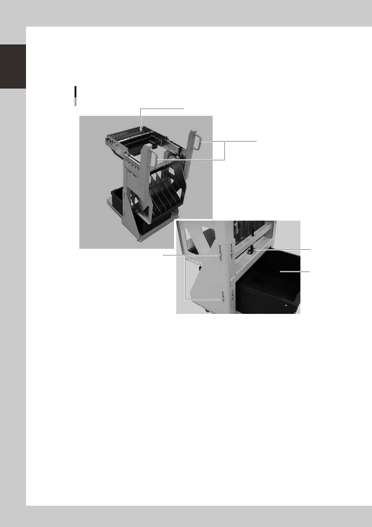
4.1.2 Feeder exchange carriage
The feeder exchange carriage allows feeder setup in advance for the next production boards. The feeders on
the feeder exchange carriage can be changed at one time.
n
Feeder exchange carriage
1
2
5
3
4
External view of feeder exchange carriage
23118-L1-00
1. Handle
Use this handle to move and position the feeder exchange carriage.
2. Feeder plate
Up to 24 SS feeders (8mm) can be installed on this feeder plate.
3. Vertical clamp bolts
If necessary to adjust the feeder plate height, loosen these bolts and change their clamping positions. (8 places)
4. Empty tape dump box (option)
This box is for catching empty tape after components have been picked up.
5. Height adjustment bolt
After loosening the vertical clamp bolts, turn this bolt to adjust the feeder plate height.
1-15
1
Part names and functions
4.2 Supplying components from trays
There are two types of external tray changers. One type, called "dYTF", supplies tray components using its pick
& place head and relay station. The other type, "sATS", utilizes a head of the connected surface mounter.
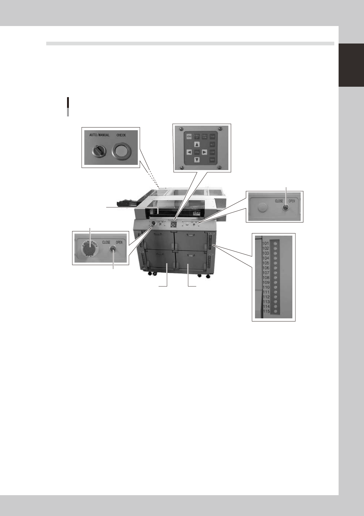
4.2.1 dYTF main unit
Major part names and their functions of dYTF are explained below.
dYTF main unit
Magazine door side
7. Pallet indicator
1. Safety cover
2. Magazine door (stage 1)
3. Magazine door (stage 2)
4. Emergency stop button
5. Door switch (stage 1)
5. Door switch (stage 2)
6. Teaching panel
8. Conveyor operation switch
23120-L1-00
1. Safety cover
When this cover is opened with the power on, it triggers emergency stop. Keep this cover closed during operation.
2. Magazine door (stage 1)
Open this door when replacing a pallet or a magazine on stage 1. The upper door is for Magazine 1 and the lower door
is for Magazine 2.
3. Magazine door (stage 2)
Open this door when replacing a pallet or a magazine on stage 2. The upper door is for Magazine 1 and the lower door
is for Magazine 2.
4. Emergency stop button
Pressing this button triggers emergency stop, the same as the emergency stop buttons on the mounter.
5. Door switch
Placing this switch in "OPEN" unlocks the magazine door, so you can open it. When this switch is in "CLOSE", the door
is locked and the door switch lamp lights up.
6. Teaching panel
Use the operation keys on this panel when teaching the tray component positions on a pallet.
1-16
1
Part names and functions
7. Pallet indicator lamp
The indicator lamp for the pallet No. set in the parts information is lit up. When the tray components on a pallet are used
up, the indicator lamp for that pallet No. flashes (see below). A total of 60 indicator lamps are provided since 15
indicator lamps are used for each magazine.
After you set new pallets in the magazines, press the flashing indicator buttons to reset them.
n
Relation between pallet indicator numbers and magazines
Pallet indicator number Magazine
1 to 15 Magazine 1 for stage 1
16 to 30 Magazine 2 for stage 1
101 to 115 Magazine 1 for stage 2
116 to 130 Magazine 2 for stage 2
n
Pallet indicator lighting pattern
Pallet condition Component condition Indicator status
One component type on one pallet
Components have been supplied. ON
Used up all components. Flashing
Components are currently being used. ON
Two or more components types on
one pallet
All components on pallet have been supplied. ON
Used up all components. Flashing
Used up at least one type of component. Flashing
Components to be used are not specified in board data. OFF
8. Conveyor operation switch
AUTO/MANUAL : Switches the conveyor operation mode between AUTO and MANUAL.
CHECK : Use this switch to make a visual check of boards when the conveyor operation is in MANUAL mode.
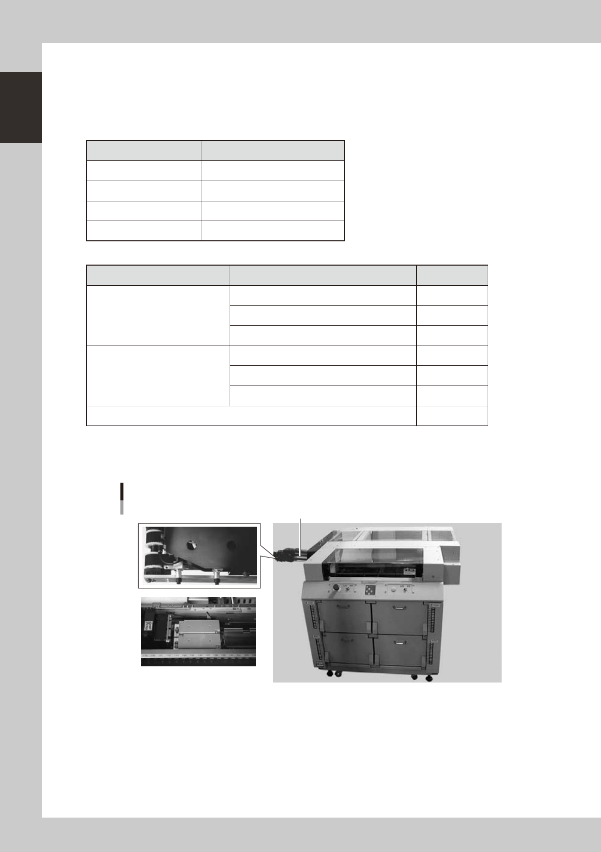
Pick & place head, relay station
3. Relay station (mounter side)
2. DX axis1. Pick & place head
23122-L1-00
1. Pick & place head
The dYTF has two dual pick & place heads. Each head picks up a tray component on the pallet and places it on the relay
station.
2. DX axis
Along this DX axis, the pick & place heads repeatedly travels between the dYTF and the mounter.
3. Relay station (mounter side)
Receives components from the pick & place heads of the dYTF. Two relay stations are provided, each having dual
receive points. This relay station moves up when the mounter heads pick up the components on the relay station.