YS100_Ope_E.pdf - 第54页
1-19 1 Part names and functions 5. Conveyor unit and component recognition system The conveyor unit used to clamp a board in mounting position is described below . Conveyor unit 5 2 1 7 6 3 Viewed from the rear side of a…
1-18
1
Part names and functions
5. Pallet indicator lamp
The indicator lamp for the pallet No. set in the parts information is lit up. When the tray components on a pallet are used
up, the indicator lamp for that pallet No. flashes (see below). Pallet indicator lamps No. 1 to No. 15 are for Magazine 1.
Pallet indicator lamps No. 16 to No. 30 are for Magazine 2.
After you set new pallets in the magazines, press the flashing indicator buttons to reset them.
n
Relation between pallet indicator numbers and magazines
Pallet indicator number Magazine
1 to 15 Magazine 1 for stage 1
16 to 30 Magazine 2 for stage 1
n
Pallet indicator lighting pattern
Pallet condition Component condition Indicator status
One component type on one pallet
Components have been supplied. ON
Used up all components. Flashing
Components are currently being used. ON
Two or more components types on
one pallet
All components on pallet have been supplied. ON
Used up all components. Flashing
Used up at least one type of component. Flashing
Components to be used are not specified in board data. OFF
1-19
1
Part names and functions
5.
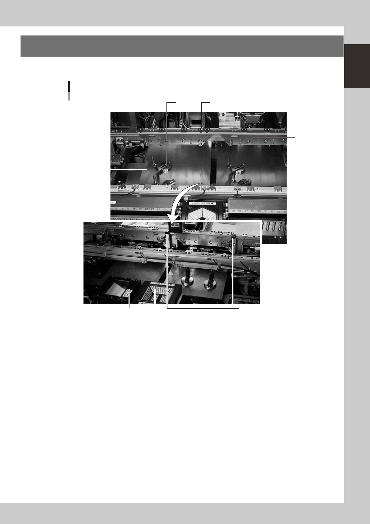
Conveyor unit and component recognition system
The conveyor unit used to clamp a board in mounting position is described below.
Conveyor unit
5
2
1
7 6
3
Viewed from the rear side of a machine
4
23110-L1-00
1. Main stopper
When a board is carried in on the conveyor, the main stopper halts travel of the board in the component mounting
position. (Double stopper is optional.)
2. Push-up plate
The push-up plate clamps the board up against the conveyor rails, with the supporter pins attached by magnet on the
push-up plate.
3. Push-up pins
These pins are arranged on the push-up plate and secure the board by pushing it up from the bottom.
4. Board hold plate
These plates hold the edges of the board from above when the board is clamped in the mounting position.
5. Board edge clamp unit
This unit clamps the board by pushing its edges up against the board hold plates.
6. Multi-vision camera
One camera each is installed on the front and rear of the machine to perform component recognition.
7. Coplanarity checker (option)
Works in conjunction with a multi-vision camera to measure lead linearity and coplanarity of lead components or BGA
components.
1-20
1
Part names and functions
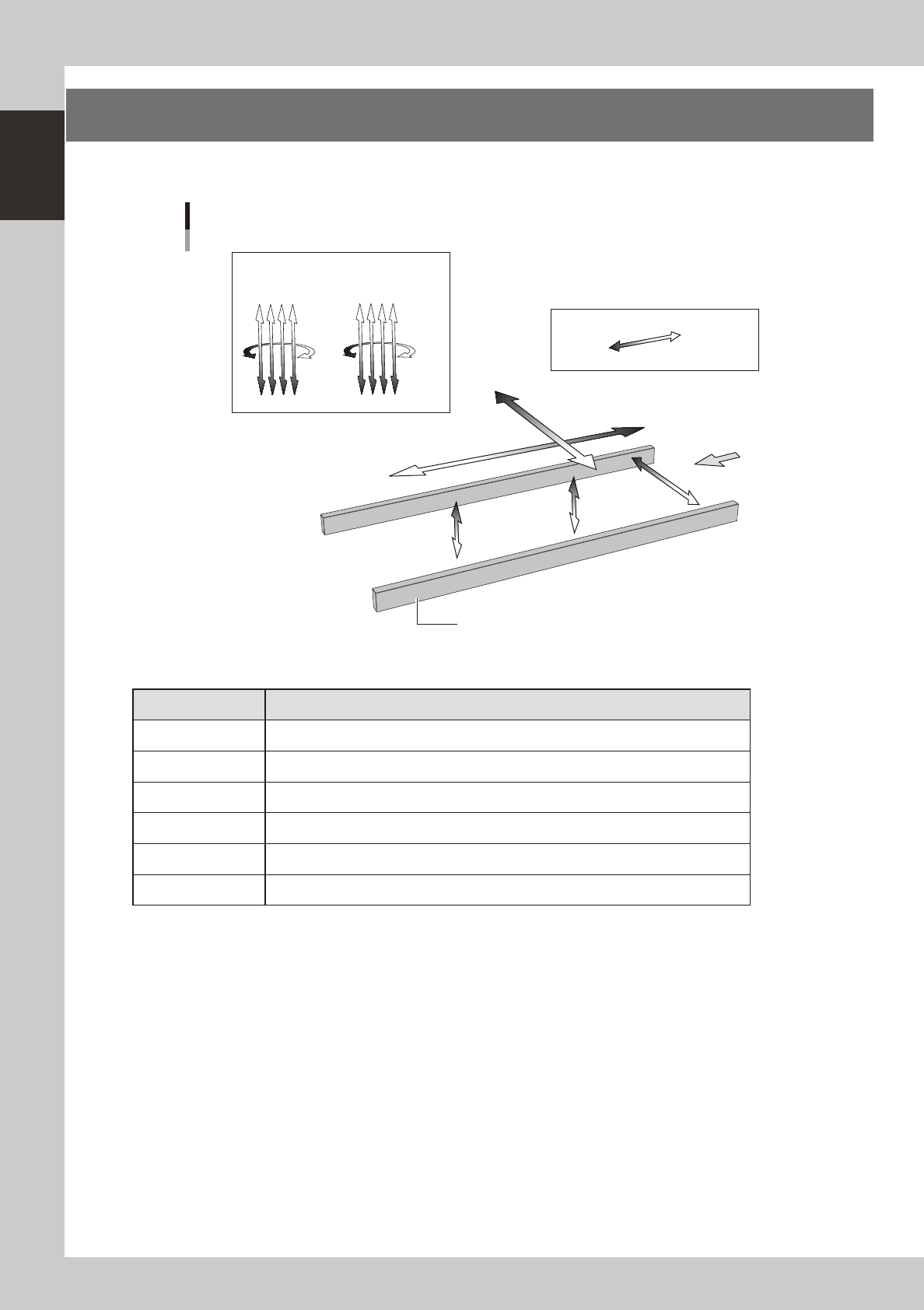
6. Axis configuration
The machine axis configuration and operation are shown in the drawing and table below.
Y axis
X axis
W axis
PU2 axis
(option)
PU1 axis
Plus direction
Minus direction
Board
Conveyor rail
R2 axis R1 axis
Head
Axis configuration
Z1Z2Z3Z4
Z5Z6Z7Z8
23111-L1-00
n
Function of each axis
Axis Function
X Moves the head assembly in parallel with the board flow.
Y Moves the head assembly perpendicular to the board flow.
Z1 to Z8 Controls the height of each head.
R1, R2 Rotates the nozzle shafts of each head.
W Changes the conveyor width.
PU1, PU2 (option) Moves the push-up plate vertically.