YS100_Ope_E.pdf - 第56页
1-21 1 Part names and functions 7. Blow station One blow station is installed in each stage. The blow station blows high-pressure air internally through the nozzles and shafts to blow away dust and grit and clean the noz…
1-20
1
Part names and functions
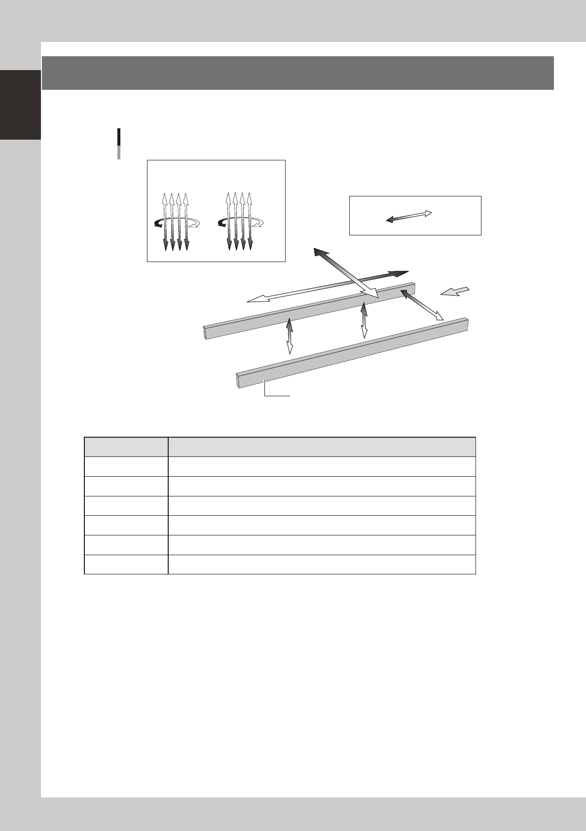
6. Axis configuration
The machine axis configuration and operation are shown in the drawing and table below.
Y axis
X axis
W axis
PU2 axis
(option)
PU1 axis
Plus direction
Minus direction
Board
Conveyor rail
R2 axis R1 axis
Head
Axis configuration
Z1Z2Z3Z4
Z5Z6Z7Z8
23111-L1-00
n
Function of each axis
Axis Function
X Moves the head assembly in parallel with the board flow.
Y Moves the head assembly perpendicular to the board flow.
Z1 to Z8 Controls the height of each head.
R1, R2 Rotates the nozzle shafts of each head.
W Changes the conveyor width.
PU1, PU2 (option) Moves the push-up plate vertically.
1-21
1
Part names and functions
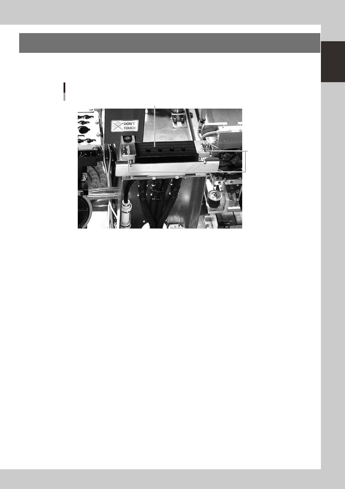
7. Blow station
One blow station is installed in each stage. The blow station blows high-pressure air internally through the
nozzles and shafts to blow away dust and grit and clean the nozzles.
Blow station
Blow station
Sensor for detecting
nozzles left on blow station
23117-L1-00
1-22
1
Part names and functions
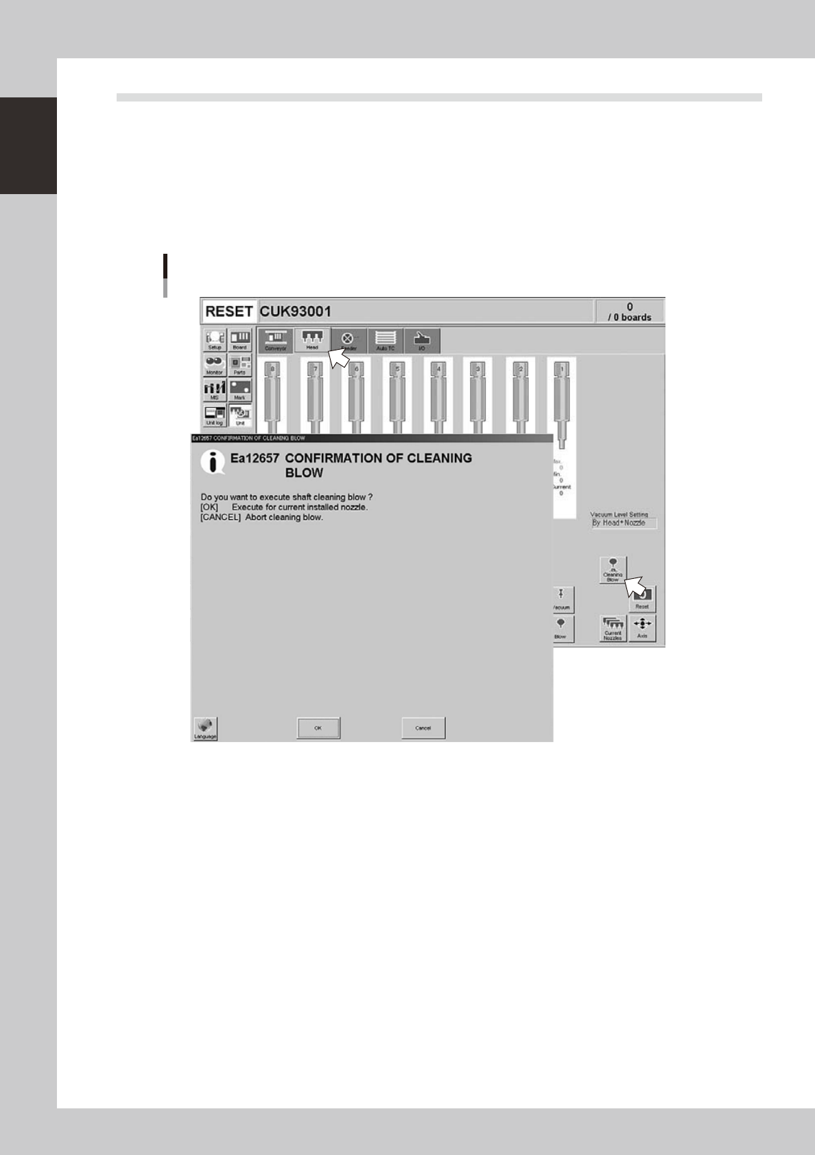
7.1 Performing a nozzle shaft blow
This section explains how to manually perform a nozzle shaft blow at any desired timing.
1
Open the [Unit] – [Head] tab screen.
2
Press the [Cleaning Blow] button.
A confirmation dialog box appears asking whether to perform nozzle shaft blow.
Press the [OK] button to perform nozzle shaft blow and proceed to the next step. If you want to cancel
nozzle shaft blow, press the [Cancel] button.
Nozzle shaft blow
24100-L1-00