YS100_Ope_E.pdf - 第65页
1-30 1 Part names and functions 9.2 QFP dump station T he QFP dump station (hereafter called dump station) is a QFP recovery convey or designed to attach to the feeder plate of a Y AMAHA surface mounter . If a QFP is jud…
1-29
1
Part names and functions
9. Other options
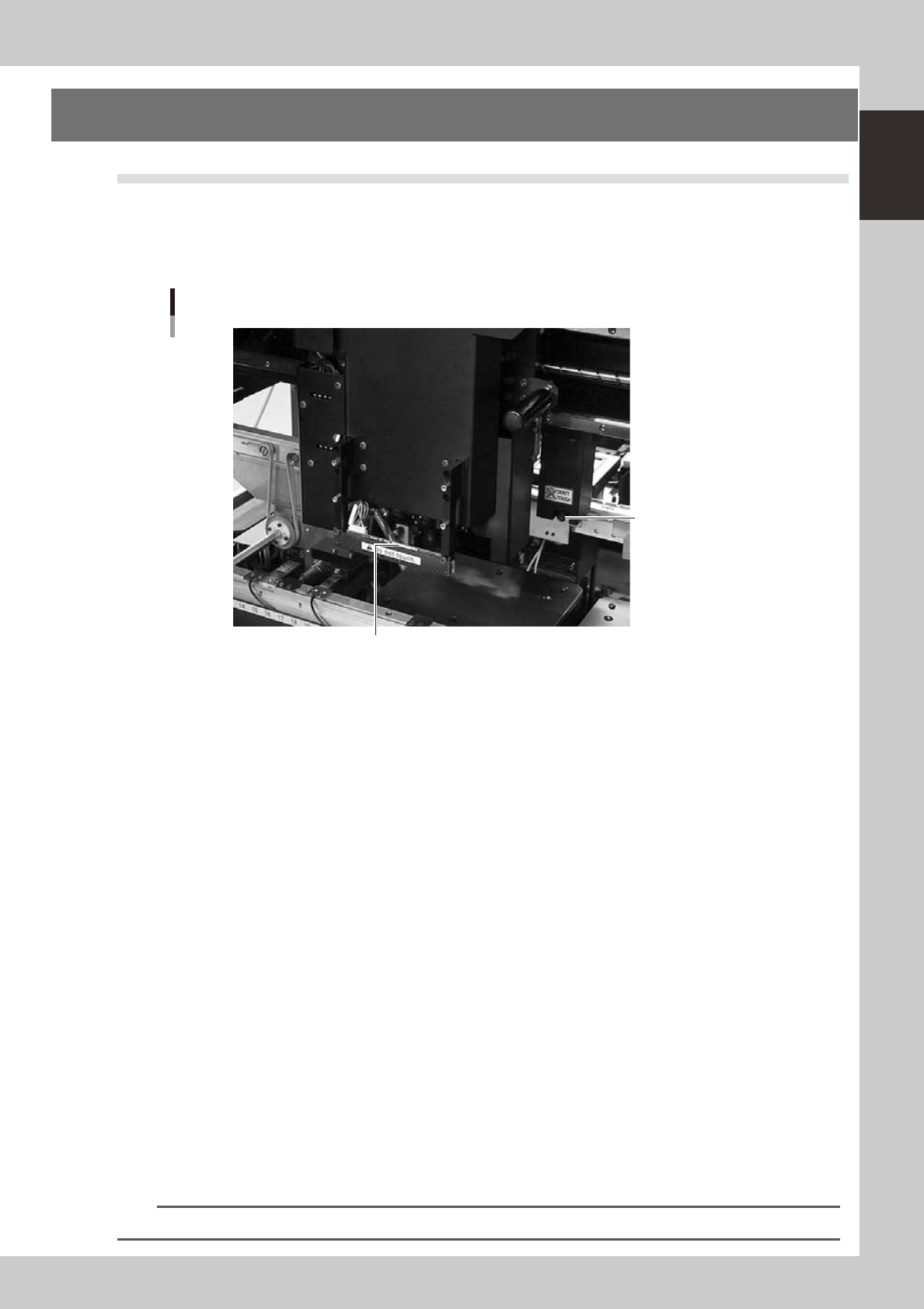
9.1 Side-view camera
The side-view camera is installed on the X-axis at the front of the multi-view camera. The side-view camera
recognizes horizontal images such as for the component pickup status, by using lighting installed for the
side-view camera. This allows the machine to detect component pickup errors and abnormal pickup, or find
dirt or debris adhering to the nozzle.
Side-view camera
Side-view camera
Lighting unit (with cover removed)
23114-L1-00
The side-view camera has the following functions:
n
Pickup error detection function
Normal mode
Detects component pickup errors to prevent "no placement errors".
Normal mode operates even when nozzles are changed after nozzle cleaning, etc.
Detail mode
Detects component pickup errors to prevent "no placement errors".
Checks for abnormal component pickups such as tilted, vertical or horizontal pickups based on the component thickness
tolerance set by the users.
n
Dirty nozzle sensing function
If the side-view camera shows "no component" even when the multi-view camera shows "component present", the
machine determines that the nozzle tip is "dirty" and a warning message appears. This serves as an accurate guide for
nozzle cleaning periods.
n
Component discard skip
This function skips the discard operation when the side-view camera shows "no component".
This eliminates unneeded operation when no component was picked up and prevents a loss of cycle time during
production.
n
Remaining component check function
This detects whether a component still remains at a nozzle tip after components were mounted or discarded.
n
Inverted component check function
In the recognition process after a component is picked up by a nozzle, this function checks if the front and back sides of
the component are inverted. It also simultaneously checks if that component size fits within the angle-of-view of the
side-view camera.
An error message appears if recognition shows the component front and back sides are inverted or that component will
not fit within the angle-of-view.
n
NOTE
Refer to "Programming Manual" for side-view camera parameter settings.
1-30
1
Part names and functions
9.2 QFP dump station
The QFP dump station (hereafter called dump station) is a QFP recovery conveyor designed to attach to the
feeder plate of a YAMAHA surface mounter. If a QFP is judged defective by vision camera recognition, that
QFP is temporarily placed on this dump station without being damaged. The QFP placed on the dump station
is then conveyed back at a specified feed pitch. When the dump station becomes full, the memory counter or
overflow sensor detects it and displays an error message before the next defective QFP is returned to the dump
station.
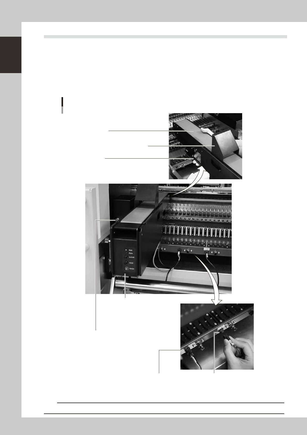
Photographs below show major parts and functions of the dump station.
Clamp lever
Use this lever to lock or unlock the dump station to
the feeder plate.
DUMP harness (signal cable)
Used to interface between the dump station
and the mounter for exchanging signals.
FEEDER harness (power supply cable)
Supplies power to the dump station from
the mounter.
Manual operation panel
Use the switches on this operation panel
to set the feed pitch, move the belt at the
specified pitch and clear the count.
The LED lamps also show the
operation status.
Overflow sensor (option)
QFPs placed on the dump station
are carried back by the belt conveyor.
When a QFP arrives at the end of
the dump station, this overflow sensor
detects it and displays an error message.
Conveyor belt
Conveys QFPs placed on the dump station at a
specified feed pitch.
Safety cover
Major parts and functions
23104-L1-00
n
NOTE
For how to use the QFP dump station, refer to the option manual "QFP dump station".
1-31
1
Part names and functions
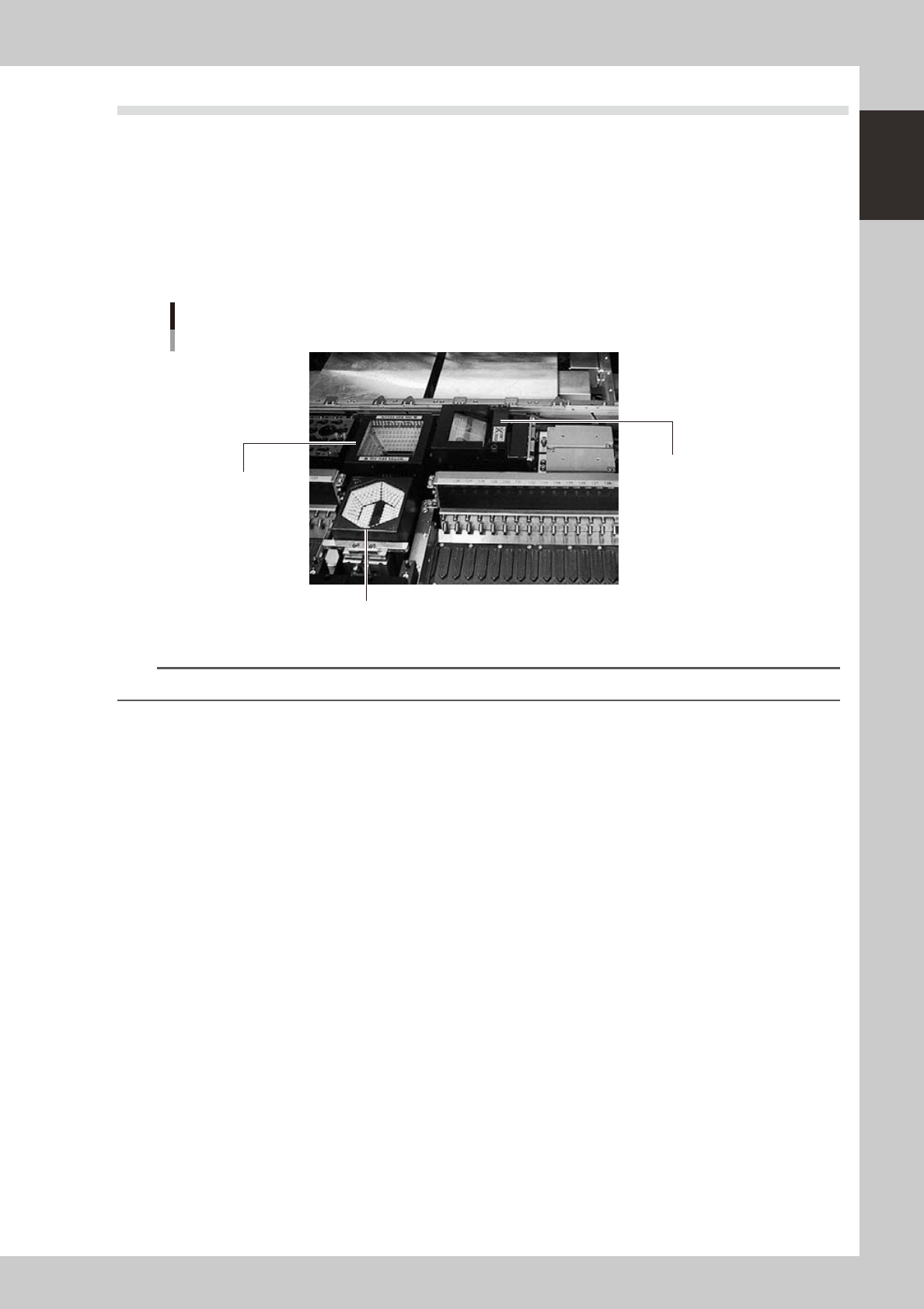
9.3 Coplanarity checker
The coplanarity checker measures lead linearity and coplanarity of QFP/SOP leads or BGA bumps at high
speeds, and determines "pass/fail".
The coplanarity checker has the following two functions:
• Coplanarity check
Inspects uniformity of the lead bottom against the seating plane of components having wire leads or solder balls.
• Component recognition height check
Prevents lead components from being mounted in an inverted position.
Coplanarity checker
Multi-vision camera (standard)
Coplanarity checker
Single-vision camera
23128-L1-00
n
NOTE
For instructions on how to use the coplanarity checker, refer to the YS series programming manual.