YS100_Ope_E.pdf - 第66页
1-31 1 Part names and functions 9.3 Coplanarity checker T he coplanarity checker measures lead linearity and coplanarity of QFP/SOP leads or BGA bumps at high speeds, and determines "pass/fail". T he coplanarit…
1-30
1
Part names and functions
9.2 QFP dump station
The QFP dump station (hereafter called dump station) is a QFP recovery conveyor designed to attach to the
feeder plate of a YAMAHA surface mounter. If a QFP is judged defective by vision camera recognition, that
QFP is temporarily placed on this dump station without being damaged. The QFP placed on the dump station
is then conveyed back at a specified feed pitch. When the dump station becomes full, the memory counter or
overflow sensor detects it and displays an error message before the next defective QFP is returned to the dump
station.
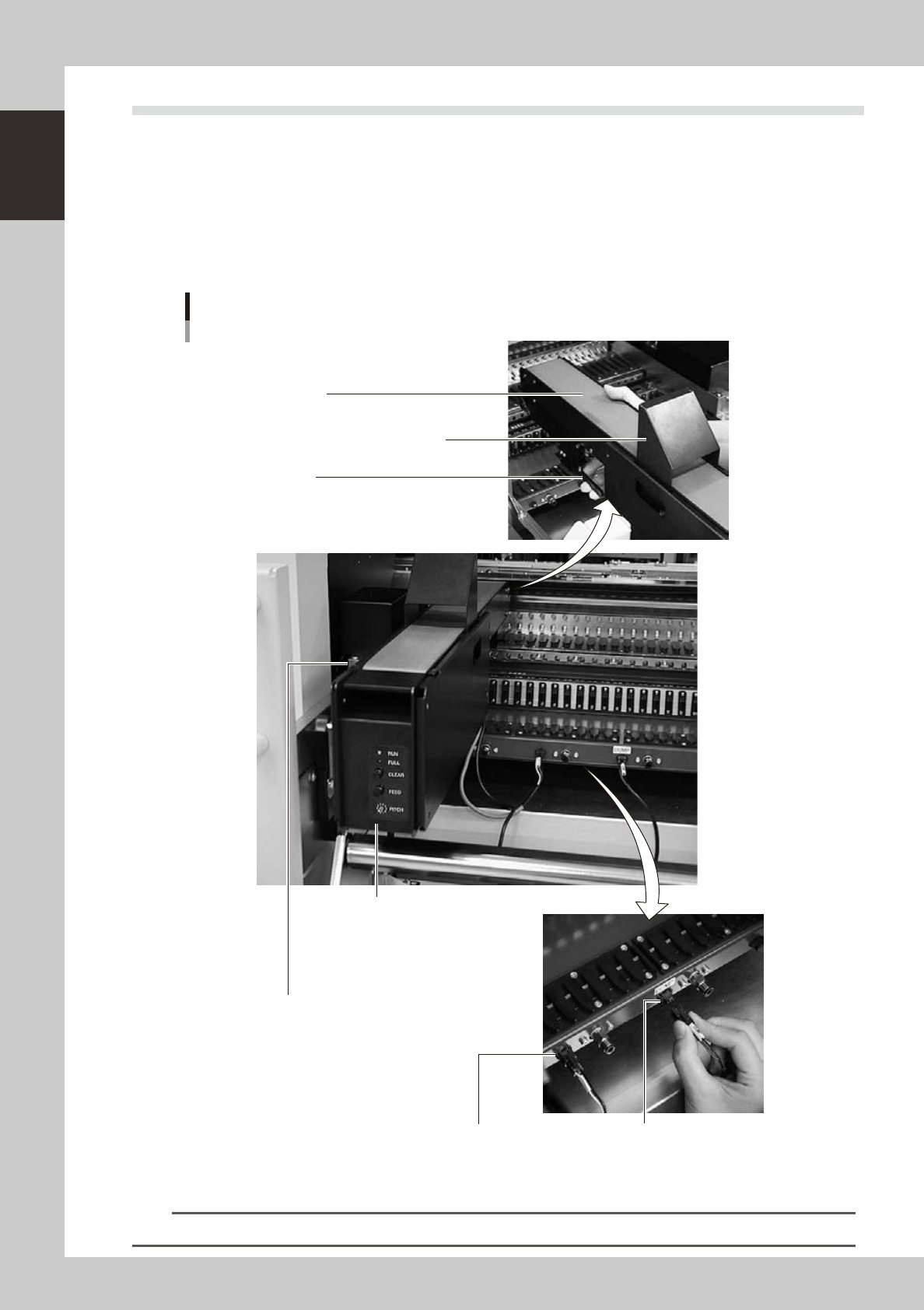
Photographs below show major parts and functions of the dump station.
Clamp lever
Use this lever to lock or unlock the dump station to
the feeder plate.
DUMP harness (signal cable)
Used to interface between the dump station
and the mounter for exchanging signals.
FEEDER harness (power supply cable)
Supplies power to the dump station from
the mounter.
Manual operation panel
Use the switches on this operation panel
to set the feed pitch, move the belt at the
specified pitch and clear the count.
The LED lamps also show the
operation status.
Overflow sensor (option)
QFPs placed on the dump station
are carried back by the belt conveyor.
When a QFP arrives at the end of
the dump station, this overflow sensor
detects it and displays an error message.
Conveyor belt
Conveys QFPs placed on the dump station at a
specified feed pitch.
Safety cover
Major parts and functions
23104-L1-00
n
NOTE
For how to use the QFP dump station, refer to the option manual "QFP dump station".
1-31
1
Part names and functions
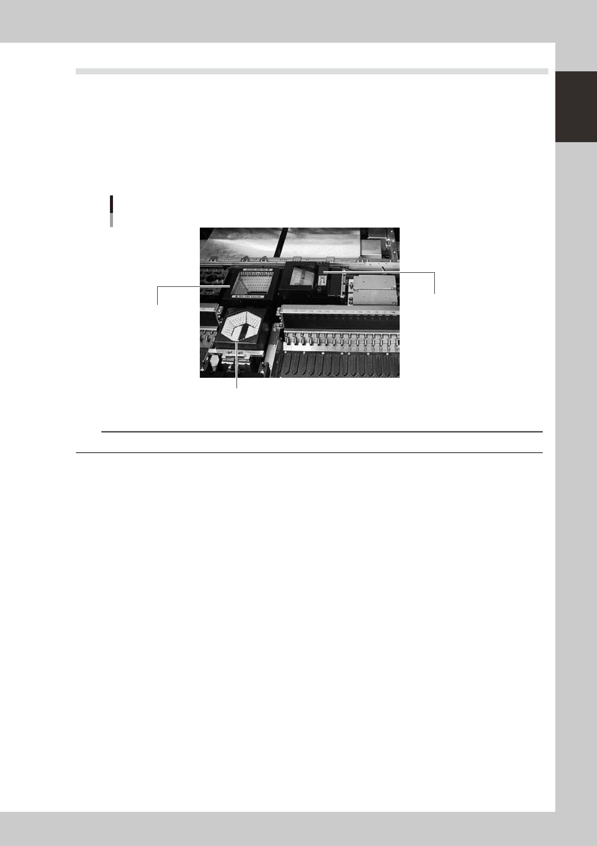
9.3 Coplanarity checker
The coplanarity checker measures lead linearity and coplanarity of QFP/SOP leads or BGA bumps at high
speeds, and determines "pass/fail".
The coplanarity checker has the following two functions:
• Coplanarity check
Inspects uniformity of the lead bottom against the seating plane of components having wire leads or solder balls.
• Component recognition height check
Prevents lead components from being mounted in an inverted position.
Coplanarity checker
Multi-vision camera (standard)
Coplanarity checker
Single-vision camera
23128-L1-00
n
NOTE
For instructions on how to use the coplanarity checker, refer to the YS series programming manual.

Chapter 2 Basic operation
Contents
1
1.1 Canceling emergency stop 2-1
1.2 Clearing an error 2-2
1.3 Typical errors and troubleshooting 2-3
0
0
2.2 Setup screen 2-13
2.3 Unit screen 2-14
3. Starting and stopping the machine 2-19
3.1 Pre-operation check 2-20
3.2 Starting the machine 2-21
3.3 Warming up the machine 2-23
5
3.4.1 Conveyor unit setup flow 2-25
3.4.2 Conveyor width 2-26
3.4.3 Board hold plates 2-27
3.4.4 Push-up pins 2-28
4. Preparing the component supply unit 2-29
4.1 Tape feeder 2-29
4.1.1 Setting the tape 2-29
4.1.2 Setting a tape feed pitch 2-34
4.1.3 Installation on a mounter 2-38
4.2 Wide multi-stick feeder 2-39
4.2.1 Installation of tracks and sticks 2-39
4.2.2 Installation on a mounter 2-42
4.3 Tray changer 2-43
4.3.1 Setting the component trays in the pallet 2-44
4.3.2 Setting the pallet in the magazine 2-45
4.3.3 Replacing a magazine or pallets during operation (dYTF) 2-47
5. Settings on the mounter side 2-50
5.1 Setting the "Package" parameter. 2-50
5